Custom Search
|
|
 
|
||
|
SHOULDER WEAPONS LEARNING OBJECTIVE Discuss the controls, safeties, and maintenance of shoulder weapons used by the U.S. Navy. Shoulder weapons are designed to be held with both hands; they are braced against the shoulder to absorb the force of recoil and to improve accuracy. Included in this group are the M14 and M16 rifles.
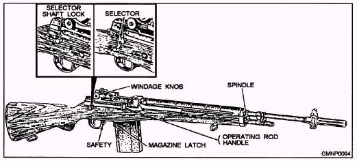
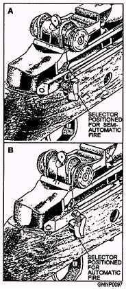
Figure 3-20.-7.62-mm M14 rifle and controls-right-front view. M14 RIFLE The M14 rifle (fig. 3-20) is a lightweight air-cooled, gas-operated, magazine-fed shoulder weapon. It is designed for semiautomatic or fully automatic fire at the cyclic rate of 750 rounds per minute. The rifle is chambered for 7.62-mm cartridges. It is designed to accommodate a 20-round cartridge magazine, the M2 rifle bipod (fig. 3-21), and the M6 bayonet (fig. 3-22). M14 Rifle Controls Figure 3-23 shows an M14 rifle equipped with a selector for automatic operation. Position the selector as shown in view A for semiautomatic fire and as shown in view B for automatic fire. In firing for semiautomatic fire, squeeze the trigger for each round fired For automatic fire, squeeze the trigger and hold. Most of the M14 rifles issued to the Navy will not be equipped with the automatic selector, only semiautomatic fire will be possible.
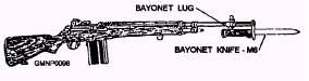
Figure 3-22.-7.62-mm M14 rifle with the M6 bayonet knife.
Figure 3-21.-7.62-mm M14 rifle with the bipod installed.
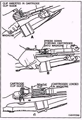
Figure 3-23.-Selector for semiautomatic and automatic fire. The location of the safety is just forward of the trigger guard. To prevent firing, press the safety back from in front of the trigger guard. To permit firing, press it forward from inside the trigger guard. The safety can only be engaged when the weapon is cocked. If a magazine is in the rifle, press the magazine latch (fig. 3-24) and remove the magazine. Pull the operating handle all the way to the rear and check to see that the weapon is free of ammunition. Then ease the operating rod forward to the locked position and move the safety to the rear (SAFE position). There are two methods of reloading an empty magazine. Figure 3-25 shows the method with the magazine in the rifle. (This method should only be used in the field since it creates a possible accidental firing situation.) After the last round is fried from a magazine, the magazine follower will engage the bolt lock and hold the bolt in the rear position. If this fails to happen, make sure you did not have a misfire, then pull the operating handle to the rear and manually depress the bolt lock (located on the left side of the receiver), ease the bolt down against it, then engage the safety. Insert a 5-round clip into the cartridge clip guide, as shown in figure 3-25, and push the cartridges down into the magazine. Four 5-round clips will fully load a magazine. After the last clip is loaded and the clip removed, pull the operating handle to the rear to release the bolt lock and then release the handle. This will let the bolt go into battery, stripping and feeding the top round into the chamber. The weapon is now ready to fire. The safest way to reload a magazine is shown in figure 3-26. Each bandolier containing the 5-round clips also contains a magazine loading tool. Insert the tool over the top rear of the magazine, as shown in figure 3-26, insert a 5-round clip into the loading tool, and press the cartridges into the magazine.
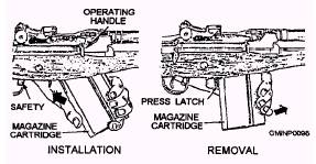
Ftgure 3-24.-Installation and removal of magazine.
Figure 3-25.-Loading magazine through cartridge clip guide. To load a full magazine into a rifle, insert the front end of the loaded magazine well into the front catch until the front catch snaps into engagement, then pull rearward and upward until the magazine latch locks the magazine into position (fig. 3-24).
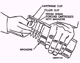
Figure 3-26.-Loading magazine with a loading tool. The gas spindle valve (fig. 3-27) controls the gases used in firing the rifle. When the slot of the spindle valve is in the vertical or ON position (upper view), the valve is open and directs gases to the operating piston for ordinary functioning of the rifle. When the slot is in the horizontal or OFF position (lower view), the spindle valve is closed. This permits the full pressure of the gas to be used in propelling a rifle grenade or line-throwing projectile. The rear sight controls consist of a windage knob and pinion assembly. (See fig. 3-20.) The function of the windage knob is to adjust the sight laterally. To move the sight to the right, turn the knob clockwise; to the left, counterclockwise. The pinion assembly adjusts the sight aperture vertically. Turn the pinion clockwise to raise, counterclockwise to lower. |
 |
|
|
||