Custom Search
|
|
 
|
||
|
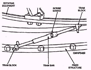
Establishment of Bench Mark and Tram Readings The sixth major alignment step is the establishment of bench marks and tram reference readings to furnish an easy means of verifying the alignment of equipment in the future. It is necessary to have reference readings because the equipment position data dials and data transmission synchros may become misaligned due to wear, vibration, or normal maintenance. These reference readings are normally established by a shipyard or NAVSEA representatives after all of the system elements are aligned. The application of these reference readings will be discussed further in the next section of this chapter. Performance of Dynamic Train Alignment The last major step is the train alignment between the reference and alignable combat system equipment not equipped with a telescope. This is accomplished by comparing equipment position with the position of the alignment reference while simultaneously tracking an isolated target. Fleet and fleet support personnel conduct this alignment. These steps are used to establish the combat system alignment. Shipboard personnel are not usually directly involved in most of this process. What we have described thus far is what takes place while a ship is being constructed or in a major overhaul. established, it is the responsibility of shipboard personnel to verify and maintain the alignment of the system. This is the part of the combat system alignment that is more familiar to most fleet personnel. ALIGNMENT VERIFICATION Several procedures are fundamental to alignment verification. In this section we will describe a typical gun mount alignment verification procedure, including tram and bench mark readings and star checks. Since each system is configured differently, we will not attempt to explain in any detail how corrections are actually made. Tram and Bench Mark Readings Once established, tram and bench mark readings give the maintenance person a ready reference to check the alignment of the equipment. Apiece of equipment will be fitted either for tramming or with a fixed telescope for sighting a bench mark. Typically, gun mounts and missile launchers are trammed, while directors are aligned to bench marks. Some systems, however, may be fitted for both. TRAM.- A gun mount is fitted with two sets of tram blocks-one set each for train and elevation. The blocks are welded, one to the rotating element and the other to a stationary element nearby. Elevation tram blocks are attached, one to the underside of the slide and the other to the trunnion support. Train tram blocks are attached, one to the bottom of the carriage and the other to the stand. Tram blocks are provided with machined plates with concave centers that fit the ends of the tram bar. The telescoping tram bar is the most common type in use and will be the only type discussed here. The telescoping tram bar consists of two parts, one sliding inside the other. The parts have a small movement with respect to each other and are extended by an internal spring. Ascribe mark on the inner part is visible through an opening in the outer part. Engraved on the edges of the opening is a zero mark. When the inner scribe mark and the outer zero mark are aligned, the tram bar is at the correct length. The tram bar is placed in the tram blocks, and the gun mount is trained or elevated to compress or expand the bar until the marks are aligned. This serves to place a known distance between two fixed points, corresponding to a specific train or elevation angle. Once this angle is determined, it becomes the reference for future alignment verification. Figure 11-3 shows a tram bar installed in a set of gun mount train tram blocks. Tram readings are taken as an average of several readings. The air drive motors are used to move the gun mount. Several readings are taken, moving the mount to compress the tram bar into alignment alike number of readings are taken, moving the mount to extend the bar into alignment. By moving the gun mount in both directions, you can detect any lost motion in the gear train. The readings are then averaged and compared to the reference readings that are inscribed on a plate normally attached to one of the trunnion supports. NOTE Elevation tram readings are almost always taken with the gun mount trained to 90 from the bearing of the high point. At any other train bearing you will get erroneous elevation readings due to the offsetting inputs of the roller path compensator. Refer to your ship's alignment manual for exact instructions for avoiding this situation. BENCH MARK- The bench mark is used much the same as tram readings. The equipment to be aligned trains and elevates to align the telescope cross hairs with the bench mark. The bench mark, however, may be some distance from the equipment you are aligning. This increases the probability that the bearing to the bench mark will change in relation to your equipment due to hull distortion. No alignment adjustments should ever be performed based on a single tram or bench mark reading.
Figure 11-3.-Tram bar and tram blocks. Star Checks Star checks are used to verify parallelism between elements of the combat system and the WCRP. To illustrate this process, we will assume that the gun director is also the WCRP. We will now align the gun mount to the director. To begin with, you can fit the gun with a borescope and all the ballistic and parallax corrections are set at zero by the GFCS. The borescope is inserted into the breech of the gun and its cross hairs aligned with the axis of the bore. In the evening, a celestial body (star) is selected, and the directories moved to track the star with its optics. Be careful not to choose a satellite. Satellites show up early and are usually very bright. This makes them tempting choices for star checks. However, once you have locked onto a satellite, you will find that it moves very quickly across the sky, making it difficult to track. The gun is driven simultaneously with the air drive motors to track the same star through the borescope. Once the star can be seen through the optics of both the gun and the director, each is moved to pass the vertical or horizontal cross hair over the star. When the star is centered in the cross hair, the person at the telescope gives a "MARK." When both the director and the gun MARK at the same time, all the movement is stopped and the dials are read This is done several times from each direction from the bottom and the top in elevation and from the left and the right in train. Each crew then averages their train and elevation readings individually. The averages are compared and the gun is adjusted to the director if the error is out of tolerance. Each time this is accomplished, the results of the verification, as well as any adjustments, are recorded in the Combat Systems Smooth Log. Refer to Align Theory, SW225-AO-MMA-010/OP762, and the appropriate volume of the SW225-XX-CSA-010 series of publications pertaining to your ship type for further information on combat systems alignment procedures. |
 |
|
|
||