Custom Search
|
|
 
|
||
|
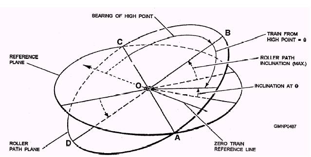
Establishment of Parallelism The third major alignment step is the establishment of parallelism between the roller path planes (RPPs) of aIl the equipment in the combat system. This step is also accomplished during initial construction. It is accomplished again as new systems are added or old equipment is replaced. The steps necessary to achieve the required degree of parallelism are foundation machining, inclination verification, and interequipment leveling. FOUNDATION MACHINING.- Before the combat system equipment is installed aboard ship, the equipment foundations are machined so that the planes of the foundations are parallel, within tolerance, to the reference plane and then smoothed to the required flatness. When the equipment is mounted aboard ship, the RPPs will not be precisely parallel. It is not possible under normal conditions to attain perfect accuracy in machining or in the construction of equipment. There will always be some error. However, once machined within tolerance, there are devices incorporated into most equipment that can be adjusted to compensate for roller path alignment error. These devices are discussed later. INCLINATION VERIFICATION.- Inclination verification consists of the measurement of the tilt between equipment RPPs of the equipment in the combat system and the reference plane. Figure 11-1 shows a plane tilted with respect to the reference plane. Note that the inclination varies with the bearing. In the direction of line OA, the inclination is zero. Inclination increases gradually in the direction of line OB until it reaches maximum positive angle at 90 from line OA. Point B is the bearing of the high point (Bhp). Point D is a negative angle, proportionate to the positive angle of point B. All the References to roller path alignment are expressed in terms of the bearing and inclination of the high point. The tilt of the RPP is determined by using clinometers or similar devices. INTEREQUIPMENT LEVELING.- YOU can accomplish equipment leveling through the use of leveling rings, shims, adjusting screws, equipment adjustments, or offset by software.
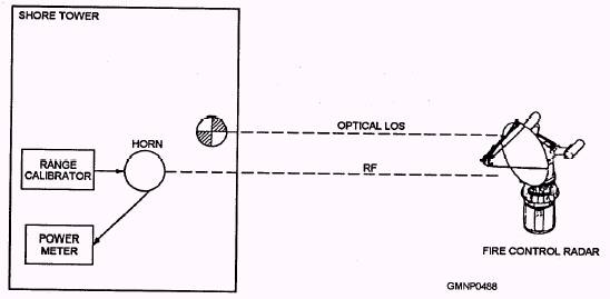
Figure 11-1.-Variation of roller path inclination with bearing. A common device used to offset the effects of roller path misalignment is the roller path compensator. The roller path compensator is incorporated into the elevation receiver-regulator of most gun mounts. It is connected through gears and linkages to the train drive unit. The roller path compensator is set with the bearing and magnitude (in minutes) of the high point. As the gun moves in train, the compensator is moved and either adds or subtracts from the elevation order the number of minutes necessary to cancel out the roller path error at that bearing. For further information on roller path alignment, see NAVSEA OP-762, chapter 5. Performance of Fire Control Radar RF-Optical Alignment The fourth major alignment step is the verification of fire control RF-optical alignment (collimation). This is the alignment between the axis of the RF energy beam emitted by the fire control radar and an optical device attached to the radar antenna. During initial installation, the alignment is established and the optics are secured in place. During subsequent alignment checks, you can make adjustments to correct any errors detected. Radar collimation checks are normally conducted using a certified shore tower facility. Some radars, however, may be collimated while tracking a target. Figure 11-2 shows the essence of radar collimation.
Figure 11-2.-Radar collimation. Performance of Train and Elevation Alignment The fifth major alignment step is the performance of train and elevation alignment. This alignment is performed by fleet support personnel to make sure the pointing lines are parallel. This procedure is the same one performed by fleet personnel to verify system alignment. Two procedures can be used for train and elevation alignment. The first is the establishment of train and elevation zero (theodolite method); the second is the train and elevation space alignment (star check method). The theodolite method aligns train zero to the center-line reference plane and elevation zero to the roller path plane of the equipment. The more familiar star check method establishes parallelism between combat system elements by having them all sight on a celestial body, then aligning their dials to match those of the weapons control reference plane (WCRP). The star check method will be discussed further in the next section of this chapter. |
 |
|
|
||