Custom Search
|
|
 
|
||
|
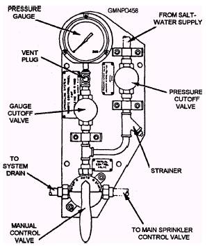
Hydraulic Control System The components of the hydraulic control system are located on the local and remote control panels. (See fig. 8-28.) Various manual shutoff valves and strainers are used in the system. They isolate certain components during maintenance procedures and filter marine growth in the saltwater supply. Most of the valves are manufactured by the Cla-Val Company and are known by their Cla-Val designation. LOCAL AND REMOTE CONTROL VALVES.- The local and remote manual control valves (fig. 8-32) are lever-operated rotary valves. Each one has three positions: OPEN, NEUTRAL, and CLOSED. The operating handle has a spring-loaded lever behind it. The lever actuates a locking pin that extends into a recess in the body of the valve. Three separate
Figure 8-32.-Remote control panel. recesses or holes allow the valve to be locked in any of its three positions. Installed between the handle and the lever is a rectangular locking key. The key is secured in place by easily broken safety wire (lead-wire seal). The locking key prevents accidental sprinkler activation since the handle and lever cannot be squeezed together with the key in place. If they cannot be squeezed, the locking pin cannot be retracted and the handle will not turn. INLINE CHECK VALVES.- Four inline check valves, designated Cla-Val No. 81M, are located on the local control board. (See fig. 8-28.) They are spring-loaded check valves that open wide when salt water flows in the proper direction (with the arrow). They close tight when salt water flows against the arrow. By preventing backflow to other stations, these check valves permit the sprinkler system to be activated from more than one station. HYDRAULICALLY OPERATED CHECK VALVE.- The hydraulically operated check valve is designated Cla-Val No. 81PM-1 (fig. 8-28). It is a normally closed, globe-type check valve that becomes functional only during the stop cycle of sprinkler operation. When fire main is ported to the upper chamber of the valve, its diaphragm lifts and opens the bottom chamber. Fire main from the top of the main sprinkler control valve is then ported out unrestricted to drain line #3. This action permits the main valve to close under spring pressure, which secures sprinkler operation. DRAINS AND ORIFICES.- The hydraulic control system has three drain lines and two orifice restrictions (fig. 8-28). The drain lines are normally located so that they can discharge into a portable container (bucket). The lines should be numbered and tagged so that they can be quickly identified. Drain lines #1 and #2 contain .098-diameter-orifice plates. The orifices (holes), drilled through flat metal plates, serve two purposes. The primary purpose of the orifices is to prevent a buildup of saltwater back pressure in control system piping. Back pressure is normally caused by valve leakage. Eventually, this back pressure could be enough to activate the system. On your daily magazine inspection, you will notice a puddle of water on the deck or in the bucket. Report it so that repairs can be made. The secondary purpose of the orifices is to vent operating pressure from the hydraulic control system when it is returned to AUTO or NEUTRAL. Main Sprinkler Control Valve The main sprinkler control valve is located inside the magazine. The valve (fig. 8-33) is a diaphragmoperated, normally (spring) closed, globe-type valve. The upper diaphragm in the bonnet chamber is raised or lifted by a minimum of 40-psi fire main pressure. As it lifts, the lower disc is pulled off its seat. Fire main supply is then free to flow to the sprinkler heads. The upper end of the valve stem can be seen in a glass sight tube. It provides a visual indication of the condition of the stem (stem down, valve closed; stem up, valve open). A removable cover is located on the bottom side of the body of the valve. Normally, the cover remains installed. During any maintenance testing or repair work, the cover is unscrewed and replaced with a special test casting (fitting). The test casting is so shaped that it extends up to the lower seat of the disc. When the disc lifts, the fire main is prevented from flowing to the sprinkler heads by the body of the test casting. The test casting also has a removable cap. When unscrewed, it may be replaced by a standard fire hose and fitting. After the system activates, the fire main flows through the hose and is discharged over the side. This process flushes the saltwater piping of the hydraulic control system. The test casting MUST be installed before any work is performed on the sprinkler system. The test casting MUST be removed after the job is completed. These two "rules" are extremely important. |
 |
|
|
||