Custom Search
|
|
 
|
||
|
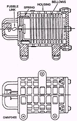
Automatic Control System The automatic or thermopneumatic control system used on this sprinkler system is similar to that of a CO2 system. The fusible link of the sprinkler HSDs (fig. 8-29) melts at 160F (3) and functions the same way as that in the CO2 system. Each HSD will also have its own circle seal check valve. Groups of HSDs can be connected to a common manifold. Each manifold will also have its own vented check valve. Transmission line tubing is the 1/8-inch OD rockbestos style.
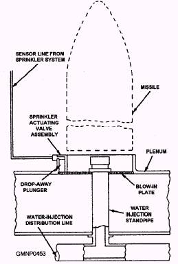
Figure 8-27.-Mk 26 GMLS water injection system.
Figure 8-29.-Heat-sensing device (HSD).
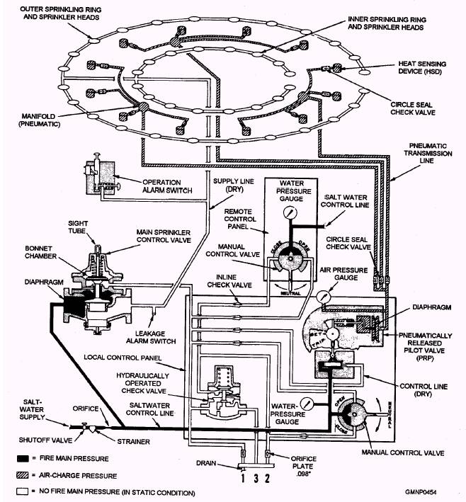
Figure 8-28.-Dry-type sprinkler system schematic; in static condition.
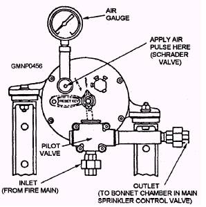
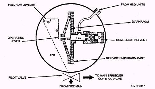
Figure 8-30.-Pneumatica1ly released pilot valve (PRP). PNEUMATICALLY RELEASED PILOT VALVE.- The pneumatically released pilot (PRP) valve (fig. 8-30) is the main component of the hydraulic control system. It is shock-mounted to the local control panel inside the magazine or RSR. The PRP valve, in response to the pneumatic pressure signal from one or more HSDs, starts automatic sprinkler activation. The outer body of the PRP valve is a circular bronze housing. Inside the housing is an operating mechanism, a diaphragm, and a compensating vent (fig. 8-31). The operating mechanism is a spring-loaded lever device connected to the diaphragm. The slightly flexible diaphragm is mounted inside an air chamber of the housing. The back side of the diaphragm chamber (or case) is connected to the HSD tubing network. The front side of the diaphragm is open to the interior of the PRP valve housing. The compensating vent connects to the backside of the diaphragm chamber. Its purpose is to "leak off" any small increases or decreases in air pressure around the diaphragm. These variations are caused by normal space temperature or pressure fluctuations. The slow "leak off" serves to equalize the pressure on both sides of the diaphragm. In doing so, the compensating vent prevents inadvertent PRP valve actuation. The compensating vent is factory calibrated and adjusted, so do not make any "sailor alterations" to it. Components outside the PRP valve housing include a hydraulic pilot valve, a Schrader valve, and an air-pressure gauge (see fig. 8-30). The pilot valve is installed in a saltwater line of the hydraulic control system. It rotates between a SET (closed) position and a TRIPPED (open) position. The pilot valve must be manually rotated back to its SET (closed) position with a special wrench (reset key). The Schrader valve is nothing more than an air valve stem (like that on a car or bicycle tire). It is only used during maintenance testing. Internally, it connects to the chamber area of the diaphragm. The air-pressure gauge monitors diaphragm chamber pressure ranging from O to 36 ounces per square inch (osi). PRP VALVE OPERATION.- As space temperature rises, one or more HSDs activate. They
Figure 8-31.-PRP valve; internal schematic. transmit the air-pressure impulse signal to the backside of the flexible diaphragm of the PRP valve. If the increased pressure is of such magnitude that the compensating vent cannot bleed it off fast enough, the diaphragm will bend or move inward (fig. 8-31). If the diaphragm moves far enough, it releases the lever of the operating mechanism. In turn, the lever rotates and trips the pilot valve. Salt water starts flowing through the hydraulic control system piping. |
 |
|
|
||