Custom Search
|
|
 
|
||
|
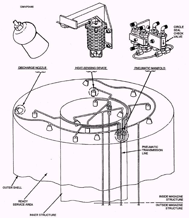
Strikedown Operations All strikedown operations contribute to the safe loading or offloading of missile canisters from the VLS. These operations require a well-trained, competent crew that strictly adheres to basic strikedown operations. Before any strikedown operation, the deck supervisor reviews the planned operations with the crew and delegates specific assignments. During strikedown operations, it is paramount that the crew maintain constant communication. All members of the strikedown crew, with the exception of the deck crew, must be personnel qualification system (PQS) certified and have a naval enlisted classification (code) (NEC) of 0981. Strikedown Procedures Because of the complexity of the procedures for strikedown operations of the VLS, they cannot be covered here. These procedures are described in detail in NAVSEA Technical Manual SW394-AF-MMO-0501VLS, revision 2, Vertical Launching System Mk 41 Mods 0/1/2 Strikedown Equipment. LEARNING OBJECTIVES: Explain the purpose and basic functions of fire suppression systems used in GMLSs. GMLS fire suppression systems are designated as auxiliary equipments within the launching system. They protect the ship and its personnel from hazardous conditions resulting from fires or the high temperatures of fires. The text discusses three basic classes of fire suppression systems used in the GMLS community: 1. Carbon dioxide (CO2) systems 2. Water injection systems 3. Dry-type sprinkler systems CO2 systems are used primarily to combat electrical fires. Fixed or installed CO2 systems normally protect the unmanned GMLS areas, such as magazines and some launchers. Portable systems (you and a 15-pound CO2 extinguisher) are normally used to protect the manned GMLS areas, such as launcher control rooms. Water injection systems are designed to direct a continuous stream of water into the exhaust nozzle of a rocket motor. Should the rocket motor accidentally ignite in the magazine, the stream of water will control the burning reaction of the propellant. The water will also cool the missile and the surrounding area. It MAY EVEN extinguish the burning rocket motor, but not necessarily. Water injection systems are also known as booster suppression or quenching systems. Sprinkler systems are designed to spray water onto the missiles in magazine stowage and handling areas of a GMLS. Sprinkler systems aid in extinguishing fires. They also cool the missiles below the temperatures that could start rocket motor ignition or warhead detonation. In covering the various GMLS fire suppression systems, we will deviate slightly from the sequence we have followed so far. Atypical or representative system will be presented. Any important differences or unique features of individual GMLSs will be noted. Mainly, component location and numbers are the greatest difference. A TYPICAL CARBON DIOXIDE SYSTEM A typical GMLS carbon dioxide (CO2) system is permanently installed (fixed) in the missile magazine area. The system is designed to detect an excessive temperature buildup and activate automatically. Once the system is activated, the entire space is flooded with a large volume of CO2 extinguishing agent. The system may also be activated manually from either a local or remote control station. Physical and Functional Description The primary pneumatic-mechanical components of a simple CO2 system include the thermopneumatic control elements and supply cylinders. The supply cylinders are equipped with control and discharge heads. The system also has other associated valves and alarm switches. Many of these components are located just outside the magazine structure. The control devices and CO2 discharge nozzles are inside. They are strategically placed near fire-prone equipments (electric motors, connection boxes, slip rings, and so on). HEAT-SENSING DEVICES.- Heat-sensing devices (HSDs) were formerly designated thermosylphon units. HSDs are the detecting units of the system (fig. 8-20). They are designed to develop a pneumatic pressure signal when space temperature increases to a preset activating point. The rate of rise in space temperature maybe rapid or slow. The HSD consists of a spring-loaded, rubber bellows housed in a mesh-style cage. The bellows is held in an extended or expanded position against a compressed spring by a fusible element. HSDs are mounted above the area they monitor. They connect to the control head of the CO2 supply cylinder by a pneumatic transmission-line network. In the event of an actual fire or explosion, a rapid rise in space temperature is experienced. The heat generated by the mishap is conducted to the air inside the HSD bellows. The air inside the bellows quickly expands and increases in pressure. This pressure "signal" is transmitted to the control head of the
Figure 8-20.-Components of a CO2 system, inside magazine structure. cylinder. The pressure-sensitive head is tripped, and the system is activated. In the event of a smoldering type of fire or a heat buildup resulting from a fire in an adjacent compartment, a slow rise in space temperature is experienced. In this case, the air inside the HSD bellows expands (as before). However, its reaction is not quick enough to trip and activate the system. For this reason a fusible element is used. HSDs are designed with a fusible link as the melting element. The link is made of a lowmelting-point metal compound similar to solder. When a certain temperature is reached, the compound starts to melt. In a GMLS CO2 system, the fusible link is designed to melt at about 160F (3). When the fusible element melts, the compressed spring around the bellows is released and allowed to expand. This action causes the bellows to collapse. The sudden compression of the HSD bellows creates a pneumatic pressure impulse signal. The magnitude of this air signal is measured in ounces per square inch (osi). The pressure impulse trips the control head and activates the system. Transmission Lines.- Transmission lines connect the HSDs to the control head. The lines are 1/8-inch OD (outside diameter) by 0.088-inch ID (inside diameter) rockbestos-covered, seamless copper tubing. Quite a few rules pertain to the correct material and installation requirements associated with these lines. Refer to Technical Manual for Magazine Sprinkler Systems for guidance when repairing or replacing transmission lines. (Although this manual is the master reference for sprinkler systems, much of its information also pertains to CO2 system requirements.) Circle Seal Check Valves.- The circle seal check valve (shown in fig. 8-20) is a brass, spring-loaded check valve. It closes against a rapid change of air pressure in one direction and opens when air pressure is applied in the other direction. One circle seal check valve is installed in each transmission line leading from an HSD. The valve is installed with its directional arrow (stamped into the body) pointing toward the control head.
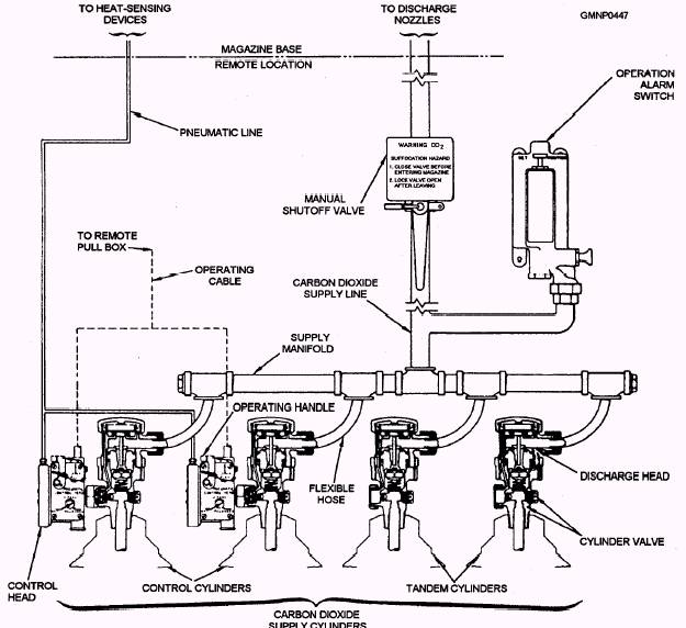
Figure 8-21.-Components of a CO2 system; outside magazine structure. The check valve prevents the rapid increase of air pressure created by one HSD (such as when its bellows collapse) from pressurizing the other HSDs. The full airpressure signal is then ported directly to the control head. This action ensures positive system activation. A vent is installed in the body of the check valve. The vent permits a slow backflow of air to bypass the main check valve element. This venting equalizes air pressure within the system in response to normal changes in ambient (surrounding) temperature. |
 |
|
|
||