Custom Search
|
|
 
|
||
|
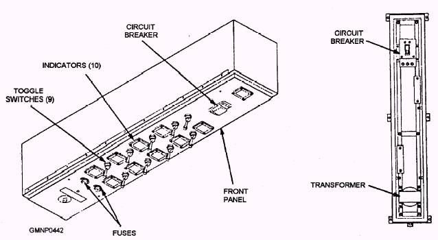
ELEVATOR ASSEMBLY.- The elevator assembly Mk 2 Mod 0 shown in figure 8-15 consists of the support structure, elevator platform assembly, control panel A19, and power distribution panel A20. These parts work together to raise and lower the elevator assembly. The support structure forms a shaft on which the elevator platform assembly travels. The shaft has lock bar sockets and guide rails that interface the platform with sensor switches on the support structure; these switches indicates the position of the platform. An alarm bell, mounted on the upper part of the support structure, sounds when the hatch or platform is in motion. An eight-section metal safety screen prevents personnel from falling into the elevator shaft and the moving platform. If the powered hydraulic pump fails, a manual hydraulic pump (fastened to the lower support structure) can be used only to dog/undog and open/close the elevator hatch. The elevator platform serves as a base for the strikedown crane. The platform, which is rectangular in shape, is mounted on a three-stage telescoping hydraulic cylinder. The cylinder raises and lowers the platform. The platform can be moved only when the crane is stowed. An emergency system, consisting of a spring set and two knurled rollers, stops the downward motion of the elevator if hydraulic pressure falls below 200 psi. The control panel A19 (fig. 8-16) is a watertight cabinet mounted on the elevator support structure just below the upper walkway, as shown in figure 8-15. The A19 control panel lever-lock toggle switches control the motor hydraulic power start-up, elevator hatch, lock bars, and elevator. These switches, except MOTOR-START and MOTOR-STOP, must be actuated and held until the desired ffunction is complete. Except for MOTOR-START and MOTOR-STOP, the operation can be stopped anytime by the release of the toggle switch.
Figure 8-16.-Control panel A19.
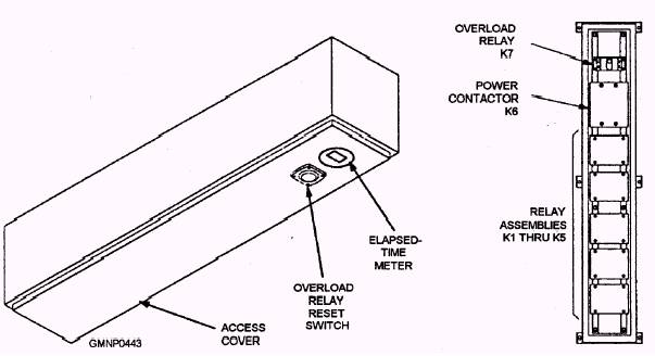
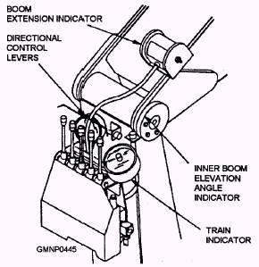
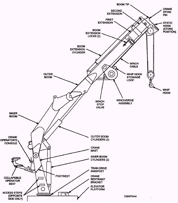
Figure 8-17.-Power distribution panel A20. The power distribution panel (PDP) A20 (fig. 8-17) routes the 440-VAC, 60-Hz, three-phase power through a three-phase power contactor to the 30-hp electric motor of the hydraulic power supply. The cabinet is watertight and mounted near the top of the elevator support structure, as shown in figure 8-15. The overload relay reset switch and elapsed time meter (that records component in-service time for the elevator) are located on the access cover. CRANE ASSEMBLY.- The Mk 1 Mod 0 strikedown crane (fig. 8-18) is a hydraulically powered, knuckled-type crane. The crane mast is bolted to the elevator platform through the drive king post. The crane mast contains the crane operator's console, collapsible operator seat, footrests, and access steps. The elevator assembly supplies the electric power for the crane indicator night lights and the hydraulic power that drives the crane. The crane has an inner and outer boom connected in series to the upper end of the mast by pivot points (referred to as knuckles). TWO parallel hydraulic cylinders pivot the inner boom at the mast, and two others pivot the outer boom at the inner boom. A duplex-type hydraulic cylinder attached to the outer boom extends and retracts the two boom extensions. The crane contains a static hook (on the bottom tip) that is secured with a stowage pin when not in use. A whip hook, on a pulley block, raises and lowers as the winch pays out or reels in the winch cable. The winch/drive assembly is hydraulically driven. The crane operator's console contains the directional control levers (fig. 8-19) used to train the crane mast, raise and lower the inner boom, raise and lower the outer boom, extend and retract the boom extensions, and raise and lower the whip hook. Four visual indicators are located near the controls. The train bearing, inner boom elevation angle, and boom extension indicators enable the operator to position the boom over any selected cell. The temperature gauge allows the operator to monitor hydraulic fluid temperatures during crane or elevator operations.
Figure 8-19.-Crane operating controls.
Figure 8-18.-VLS strikedown crane Mk 1 Mod 0 in operating configuration. |
 |
|
|
||