Custom Search
|
|
 
|
||
|
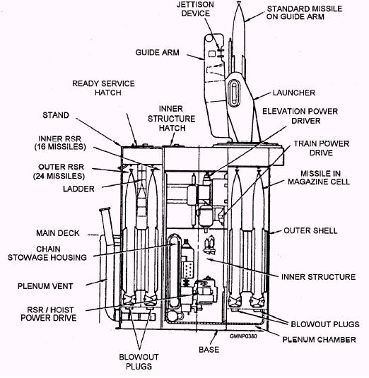
MK 13 MODS 4 AND 7 GMLS LEARNING OBJECTIVES: Explain the purpose/function of the Mk 13 Mods 4 and 7 GMLS major components. We will now study the Standard launching system by covering a launcher commonly known as the "one-armed bandit." The Mk 13 Mod 4 GMLS is installed aboard FFG-7 Oliver Hazard Perry-class ships and the Mk 13 Mod 7 is installed aboard CGN-36 California-class ships. They provide a varied tactical arsenal of missiles to engage air and surface targets. It stows, selects, identifies, loads, aims, and fires Standard SM-1, SM-2, and Harpoon missiles.
Figure 7-2.-Mk 13 Mod 4 GMLS. The Mk 13 Mod 7 GMLSs were originally built as Mods 0, 1, and 3, but because of the design changes in the control system giving the launcher Mod 4 characteristics, they are now designated as Mod 7s. The text will address the Mk 13 Mod 4 configuration. The Mod 7 has the same configuration as the Mod 4. CAPABILITIES The Mk 13 Mod 4 (fig. 7-2) GMLS can stow up to 40 missiles, one of which will be a guided missile training round (GMTR) in the rotating ready service ring (RSR) cells of the magazine. The outer ring stows 24 missiles and the inner ring stows 16 missiles. The system is capable of identifying up to seven types of missiles, A through G, plus the GMTR. The main structural units of the magazine are the base, the outer shell, the inner structure, and the stand. A plenum chamber, attached to the base, vents gases if a missile accidentally ignites in the magazine. The inner structure houses, among other components, the train and elevation power drives, the RSR/hoist power drive, the launcher relay control box, and the missile dc power supply. In operation, the RSR rotates (between the outer shell and the inner structure) to position the selected missile at the hoist station for loading onto the launcher. The missile launcher carriage has unlimited motion in train. The elevation load angle is 90. The two train load positions are 0 (inner ring) and 180 (outer ring) (fig. 7-3). Automatic pointing cutout systems prevent pointing a missile at any part of the ship. A firing cutout mechanism prevents firing missiles in areas hazardous to personnel and at the ship's structure. Individual ship's structure determines pointing and firing cutout zones. A dud-jettison unit is an integral part of the launcher guide. The dud-jettison unit ejects missiles overboard that fail to fire and are unsafe to return to the magazine. Modes of Control The Mk 13 GMLS has two modes of control: automatic control and step control. Automatic control is the normal mode for loading a missile onto the guide arm and for unloading a missile from the guide arm to the magazine. The weapons control system (WCS) selects continuous loading or single loading to load and launch missiles in automatic control. Continuous loading initiates loading and launching until the magazine is empty or until WCS baits the operation.
Figure 7-3.-Mk 13 Mod 4 GMLS, launcher load positions. Single loading initiates the same operations as continuous loading, except that after launching one missile, the launcher trains and elevates to the LOAD position to await further orders. The operation resumes when WCS orders another single loading or continuous loading. Also, if properly set up, the fire control system (FCS) can remotely light off the launching system and auto-load (or auto-unload) a selected type of missile. The launcher can be aimed and a missile fired before the GM can return from the mess decks with a fresh cup of coffee. Step control is the step-by-step sequencing and operation of the Mk 13 GMLS components by manual switching at the EP2 panel. The system can be operated in step control to load and launch missiles in a tactical situation if the automatic control circuitry becomes inoperable. Missiles may be loaded onto the guide arm in step-load and maybe unloaded into the magazine in step-unload. System components may also be cycled in step-exercise. Interlocks in the system ensure that selected step control functions are sequentially correct. Indicating lamps on the EP2 panel signal completion of each component function. The launcher train and elevation systems operate under remote and local control signals. Remote orders are generated by the FCS computer. Local orders come from synchro transmitters within the launching system control. |
 |
|
|
||