Custom Search
|
|
 
|
||
|
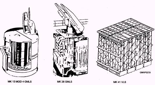
CHAPTER 7 GMLSs: PRIMARY FUNCTIONS AND DESCRIPTIONS The purpose of any delivery unit is to place (launch) a weapon into a desired flight path. That task must be done safely, efficiently, rapidly, and as frequently as the situation demands. We will discuss the major GMLSs maintained by GMs. There are other missile launching systems in use, but they are not manned by GMs. These systems include the NATO Seasparrow and the Harpoon and Tomahawk canister launchers. Before continuing, let's define the terms mark and modification, commonly abbreviated Mk and Mod, respectively. Each assembled unit of ordnance equipment is identified by a name, a mark number, a modification number, and a serial number. This information is stamped directly on the equipment or on an attached nameplate. A mark number designates a major change in design. Modification numbers are added when there has been minor, but significant, design alterations. Units of identical design have the same name, mark, and mod numbers, but are assigned different serial numbers. The missile launcher is an integral, but separate, element of the weapons system. The launcher provides support for the missile before and during launch. Initial missile flight orientation is provided by aiming the axis of the launcher along the computed line of fire. The launcher also provides two major electrical connections to the missile. One connection supplies preflight missile orders that are generated by the missile fire control system (MFCS) computer. The other connection supplies firing (ignition) voltage to the propulsion unit of the missile. The firing signal is normally initiated by the weapons direction system (WDS) and weapons direction equipment (WDE). Launchers may be rigidly attached to the ship or they may rotate in train and elevation axes. The Mk 41 Vertical Launching System (fig. 7-1) is an example of a rigid launcher. The Mk 26 and Mk 13 Mods 4 and 7 are examples of rotating axes launchers. As you study chapters 7 and 8, pay particular attention to the terminology associated with each system. For effective communication, we cannot overemphasize the necessity for using correct technical
Figure 7-1.-Major GMLSs. terminology. For example, what is the difference between a fixed rail and retractable rail? These terms refer to a common launching system component whose basic function is to stow or guide a movement of the missile. The use of correct terminology when talking about a particular system is absolutely essential. Some system components do have slang names that are generally recognized by all GMs and, if appropriate and within good taste, the manual will mention them. For more "colorful" definitions, go ask your chief! Additionally, throughout the chapter, some component descriptions will include various size dimensions. They are given only so you will have a better idea of a physical arrangement. |
 |
|
|
||