| Tweet |

Custom Search
|
|
 
|
||
|
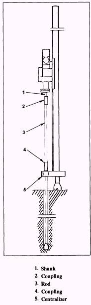
Drilling Operation Before drilling, make sure the blow air pressure gauge indicates 100 psi. Drilling procedures are as follows: 1. Open the blow control lever to admit air through the drill steel and bit. NOTE: Two types of drill bits, used in thr NCF, are the roller bead and carbide insert. 2. Start forward rotation by pushing the control lever toward the console. 3. Push the drill lever toward the console to start the drifter conclusion. 4. Push the slow feed lever to collar the hole. Collaring should be carried out by alternately moving the feed lever up and down until the bit has penetrated 3 to 4 inches into solid rock. NOTE: Make sure the hole does NOT deflect from the desired hole direction. 5. After a successful collar is made, push the rotation lever and the blow lever all the way, then push the feed lever. NOTE: Speed of drilling and rotation is automatic according to the density of the rock formation. The harder the rock, the faster the unit will drill. Use the control lever for the desired speed. CAUTION Pay attention to the vibration of the hydraulic hose in the drill. If the hose vibrates abnormally, the accumulator of the drill is damaged or the gas pressure has dropped abnormally due to a gas leakage. Pay attention to the yawing of the drill mounting. Violent yawing of the drill mounting is caused by improper feed pressure. Adjust the feed force by using the feed pressure adjusting valve. NOTE: Improper feed pressure shortens the life of the feed chain, the rod, the sleeve, and the shank. It also results in poor penetration rates. ADDING EXTENSION RODS.- Components of the rock drill, used when adding or removing extension rods, are shown in figure 14-26. Adding extension rods, commonly called drill steel, is performed as follows: 1. Feed the drifter down and hold the coupling on top of the centralizer. Engage the drifter hammer until the coupling is loose. 2. Reverse rotate and allow the drifter to back out of the coupling, then run the drifter to the top of the drill guide. Be sure to grease the drifter shank or tamper bar, and ensure the coupling remains on the drill steel down in the borehole. 3. Attach another coupling to the drifter shank or tamper bar. Add additional drill steel; forward rotate until all is coupled. 4. Lift the coupling off the centralizer. Then open the centralizer and continue drilling until the coupling has completely passed the centralizer. Once the coupling has passed, close the centralizer around the drill steel. REMOVING EXTENSION RODS.- Once the rock drill has reached the desired depth, removing the extension rods is performed as follows: 1. Clean the hole completely before removing the drill steel. 2. Move the rotation control lever to the neutral position to stop rotation. 3. Place the coupling on top of the centralizer, and allow the drill to hammer on the shank to loosen the coupling threads. 4. Shut off the drill. 5. Reverse rotate the steel from the coupling.
Figure 14-26.-Components of the drill guide. NOTE: Keep an eye on the coupling that connects the drill shank to the drill steel. This coupling will work loose faster than the lower coupling and could fall. 6. Run the drifter down to the coupling that is resting on the centralizer. 7. Forward rotate the drifter into the coupling. 8. Run the drifter with the attached coupling and drill steel to the top of the drill guide. To remove successive sections of the drill steel, you repeat the steps as outlined. NOTE: Clean and lubricate all drill steel sections and coupling before storing. After drilling four consecutive boreholes, the drill steel should be rotated or changed. SAFETY Personnel, involved in rock drilling operations, must adhere to the safety guidelines outlined in the U.S. Army Corp of Engineers, Safety and Health Requirements Manual, EM 385-1-1. Additional safety precautions are as follows: l Safety equipment, such as double-hearing protection, safety goggles, respiratory protection, hard hats, gloves, and safety boots, must be worn by all personnel that are involved in rock drilling operations. . Remember to retract the foot piece of the drill guide from the drilling face before moving the drill rig. Failure to do so can cause extensive damage to the hydraulic components of the drill guide. s Never use reverse rotation of the drill to break tight or stuck coupling joints. . Do NOT allow personnel, other than the operator, to ride on the rock drill. . Do NOT operate the drill with the coupling resting on the centralizer arms. . Do NOT move the drifter rotation control lever from forward to reverse without first stopping the drill. l When securing the drill, position the drill guide in a 90-degree vertical position. l When the operator is operating the rock drill from the operator's seat, all personnel must stay clear of the drill control console, . Visitors, unless suited properly with all safety gear, must stay clear of rock drilling operations at a distance of no less than 50 feet. l Secure all drilling operations during thunderstorm conditions. . Use gloves when handling drill steel, couplings, and bits. These components get extremely hot when used in rock drilling operations. MISCELLANEOUS CONSTRUCTION AND MAINTENANCE EQUIPMENT Floodlights, generators, lubricators, pumps, sweepers, and snow removal equipment are categorized as miscellaneous construction and maintenance equipment. This equipment is listed under the registration series USN 50-00000. |
 |
|
|
||