| Tweet |

Custom Search
|
|
 
|
||
|
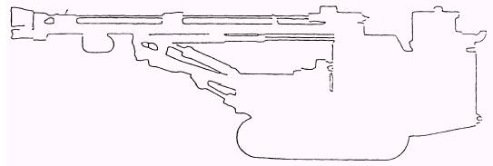
TRAVELING To travel the crawler-mounted rock drill over long distances, place the drill guide in a horizontal position, as shown in figure 14-23. When traveling in a drill pattern, keep the drill guide in a vertical position. Traveling with the rock drill, using the tramming control panel (fig. 14-24), is as follows: 1. Forward: Push both tramming control levers forward.
Figure 14-23.-Rock drill travel position.
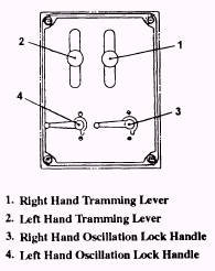
Figure 14-24.-Tramming control panel. 2. Backward: Pull both tramming control levers backward. 3. Pivot turn: Push the right or left tramming control lever forward, and the unit pivots as the opposite track works as a fulcrum. 4. Right turn: Push the left tramming control lever forward and pull the right tramming control lever backward. 5. Left turn: Push the right tramming control lever forward and pull the left tramming control lever backward. 6. Speed adjustment: The speed is controlled by adjusting the forward angles of the tramming control levers. 7. Stop: To stop the rock drill, release the tramming control levers. When the levers return to the neutral position, the machine stops automatically. At the same time, the parking brake works. After completion of traveling, lock the levers. NOTE: When working in tight areas, stay aware of your surroundings, ensuring all personnel stay clear of the rock drill when traveling and turning. Drilling with the rock drill is performed from the drilling control console (fig. 14-25). The functions of the components of the drilling control console are as follows:
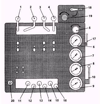
Figure 14-25.-Drilling control console. 1. Fast feed control lever: This lever is used for cleaning the hole and for changing steel. When pushed, the drill moves forward at fast speed. When pulled, the drill moves backward at fast speed. The lever returns automatically to neutral when released. 2. Drill control lever: This lever controls the percussion of the drifter. The drill pressure becomes higher in proportion to the position of the lever. 3. Rotation control lever: his lever controls the forward or backward rotation and rotation speed of the drill steel. 4. Slow speed control lever: This lever is used when drilling boreholes and coupling and uncoupling drill steel. When pushed, the drill steel moves forward at a slow speed. When pulled, the drill steel moves backward at a slow speed. 5. Feed pressure adjusting control valve: This control valve adjusts the feed pressure speed during drilling. When you pull and turn the knob to the right, the feed force increases. When you turn the knob to the left, the feed pressure decreases. 6. Feed pressure gauge: This gauge indicates the amount of discharged feed air pressure. 7. Drill pressure gauge: This gauge indicates the drill pressure during drilling. 8. Rotation pressure gauge: This gauge indicates the rotation pressure during drilling. 9. Blow pressure gauge: This gauge indicates discharged air pressure. 10. Blower control lever: This lever controls the amount of air going through the drill steel to clear the cuttings from a borehole. When the lever is turned towards the operator, the blow volume increases gradually. When the lever is turned away from the operator, the valve is opened fully. NOTE: When drilling, open the blower control lever fully. 11. Boom extension control lever: This lever extends and retracts the boom. 12. Boom lift control lever: This lever raises and lowers the boom. 13. Boom swing control lever: This lever swings the boom left or right. 14. Guide dump control lever: This lever controls the 180-degree forward and backward movement of the drill guide. 15. Guide swing control lever: This lever controls the swing of the drill. The maximum swing of the drill guide is 45 degrees to the left and 45 degrees to the right. 16. Guide extension control lever: This lever extends the drill guide for an additional extension of up to 5 feet. 17. Anti-jamming system on-off control valve: During operation, the anti-jamming system assists in keeping the drill steel from jamming in a borehole. 18. Vaposol system on-off valve: During operation, from a 40-gallon storage tank, the vaposol system throws a mist of water down the drilled hole to control dust. It can also be used while drilling to prevent a cave-in from loose material in a borehole. 19. Needle valve: The needle valve controls the amount of water to be injected into the blow air. 20. Panel lamp switch. Positioning for Drilling Positioning the rock drill is performed as follows: 1. Position the rock drill by using the traction levers. 2. Place the crawler chassis in a horizontal position, when possible, by using the track oscillation levers, and then set the oscillation lock handles to the drilling position to keep the rock drill stable while drilling. NOTE: The drill operator should approach marked boreholes straight on as much as possible. 3. Position the drill guide over the spot to be drilled. 4. Extend the guide down until the second or third track roller is just off the ground. Position the drill guide inward towards the rock drill to compensate for the pressure and angle of the boom when in position for drilling. 5. Before drilling, you must ensure the guide is vertically level by using a builders level on the front and side. |
 |
|
|
||