 |
||
|
|
||
| |||||||||||||||
|
|
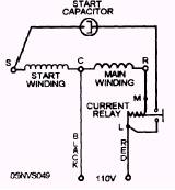
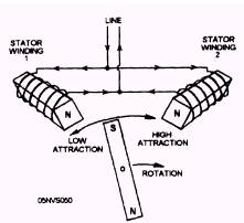
START CAPACITORS Start capacitors are connected in series with starting windings. By looking at figure 14-39, you can see the location of the start capacitor in a circuit. Because a start capacitor is placed in series with one of the two stator windings, the current will lead, as compared to the current going directly to the connected stator winding. This, in turn raises the attraction of one stator winding over the other, allowing the motor to begin turning. Figure 14-39(A) shows that stator winding 2 is stronger than stator winding 1. Therefore, the motor begins to turn in the direction of the stronger attraction. Once the initial starting of the motor is completed, the start capacitor is removed from the circuit
Figure 14-39.-Various types of capacitors.
Figure 14-39.-Motor starting. RUN CAPACITORS Run capacitors are connected in the circuit between the line side of the starting and running windings. This type of capacitor serves to provide a smoother and quieter operating motor.
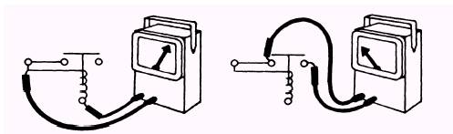
Figure 14-40.-Testing a starting relay with an ohmmeter. EQUIPMENT AND TEST PROCEDURES FOR ELECTRICAL CIRCUIT COMPONENTS The equipment and procedures for testing circuit components such as starting relays, overload protectors, and capacitors are discussed as follows. STARTING RELAYS Starting relays can be tested two ways with an ohmmeter. The meter can be used to check across the relay contacts, or it can be used to check across the relay coil. This does not apply to thermal relays. Figure 14-40 illustrates procedures for these tests. When you check the relay contacts, you must know if the contacts are normally open or normally closed. Voltage relay contacts and thermal relay contacts are normally closed, whereas current relay contacts are normally open. The meter reading should indicate continuity through voltage and thermal relays since the contacts are normally closed. On the other hand, if the meter indicates continuity through the normally open contacts of a current relay, the contacts are probably fused together. Another method of checking starting relays is by using a test line cord and fuse combination to isolate the relay. Figure 14-41 illustrates the procedure used in making this test. Obtain a capacitor of the approximate size used with the compressor motor. Connect it from the hot side of the running winding to the hot side of the starting winding. Connect the test line to the motor terminals as illustrated in the figure and plug it in. If the compressor is good it should start running. After a short time, disconnect the capacitor. The compressor should continue to speed up and run normally. This procedure has accomplished manually what a properly functioning starting relay is supposed to accomplish. If the motor failed to start normally before the check, the relay is bad. Voltage and current relay coils can also be tested for resistance with an ohmmeter. When the coil is burned out, the meter indicates no resistance or an open coil. Commercial starting relay testers are available from several manufacturers. |
|
Privacy Statement - Press Release - Copyright Information. - Contact Us - Support Integrated Publishing |