 |
||
|
|
||
|
Page Title:
Overload Protectors |
||
| |||||||||||||||
|
|
OVERLOAD PROTECTORS Questionable Klixon external overload protectors should be replaced with new ones. If the
Figure 14-41.-Procedures for checking a starting relay witha test line.
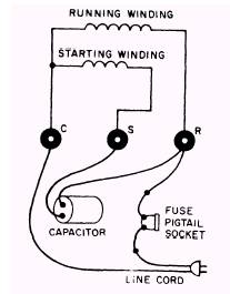
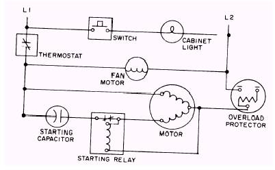
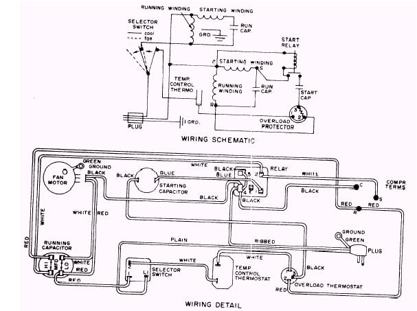
motor then operates properly, the old Klixon (protector) should be destroyed. Klixons can also be checked with an ohmmeter. Since the contacts are closed at ambient temperature, the meter should show continuity. When the meter shows an open, the Klixon should be replaced and destroyed. Internal current temperature overloads can be tested by making continuity checks. Continuity checks must be made across terminals C and S, C and R, and S and R. When both C and S and C and R are open and continuity is indicated across S and R, the protector is open. When the temperature is normal and the continuity test indicates the overload contacts are open, the motor compressor assembly must be replaced. When the operating temperature is normal, the internal current temperature overload contacts should be closed. CAPACITOR TEST The best test for a questionable motor capacitor is to try a new one of the correct size. If the motor operates properly, the old capacitor is defective and should be destroyed. Capacitors can also be tested with ohmmeter. First, the power must be Figure 14-43 is a typical schematic diagram for a hermetic electrical system. Figure 14-44 is a wiring schematic and a wiring detail for a typical room airconditioner.
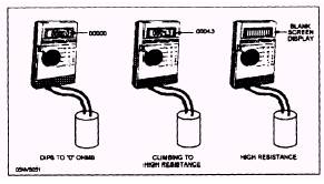
Figure 14-42.-Testing capacitors with an ohmmeter. turned OFF and the capacitor disconnected and discharged with a 2 watt 20,000 ohm resister. Set the meter on the 0 to 10,000 ohm scale and touch the meter probes to the capacitor terminals. If the digital display indicates 0 or low resistance and then climbs towards high resistance, the capacitor is good. If the display indicates 0 or low resistance and stays there, the capacitor is shorted. If the display stays blank, the capacitor is open. Figure 14-42 shows these procedures. HERMETIC ELECTRICAL SCHEMATIC WIRING DIAGRAMS All wiring circuits are built around four requirements: a source of electrons, a place for them to flow, a path for them to follow, and a load to make use of and control the flow. The schematic wiring diagram puts the symbol and line representation on paper in a manner that allows instant identification of all four requirements. It tells the service member how and why a unit works as it does. In the schematic wiring diagram, the source of electrons is a line drawn on one side of the diagram and it is usually designated as L1. Any and all points on this line have a surplus of electrons. On the opposite side, a line is drawn representing a shortage of electrons and it is usually designated as L2. There is a potential for electron flow between the two wires represented by L1 and L2. When a load is inserted between L1 and L2, current flows and the load functions.
Figure 14-43.-Typical hermetic system schematic wiring diagram.
Figure 14-44.-Wiring schematic and detail for a typical room air-conditioner.
|
|
Privacy Statement - Press Release - Copyright Information. - Contact Us - Support Integrated Publishing |