 |
||
|
|
||
| |||||||||||||||
|
|
PARTS OF WELDS For you to produce welds that meet the job requirements, it is important that you become familiar with the terms used to describe a weld. Figure 3-20 shows a groove weld and a fillet weld. `he face is the exposed
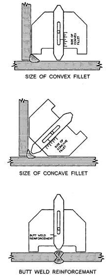
Figure 3-21.-Using a welding micrometer. surface of a weld on the side from which the weld was made. The toe is the junction between the face of the weld and the base metal. The root of a weld includes the points at which the back of the weld intersects the base metal surfaces. When we look at a triangular cross section of a fillet weld, as shown in view B, the leg is the portion of the weld from the toe to the root. The throat is the distance from the root to a point on the face of the weld along a line perpendicular to the face of the weld. Theoretically, the face forms a straight line between the toes. NOTE: The terms leg and throat apply only to fillet welds. In determining the size of a groove weld (fig. 3-20, view A), such factors as the depth of the groove, root opening, and groove angle must be taken into consideration. The size of a fillet weld (view B) refers to the
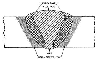
Figure 3-22.-Zones in a weld. length of the legs of the weld. The two legs are assumed to be equal in size unless otherwise specified. A gauge used for determining the size of a weld is known as a welding micrometer. Figure 3-21 shows how the welding micrometer is used to determine the various dimensions of a weld. Some other terms you should be familiar with are used to describe areas or zones of welds. As we discussed earlier in the chapter, fusion is the melting together of base and/or fuller metal. The fusion zone, as shown in figure 3-22, is the region of the base metal that is actually melted. The depth of fusion is the distance that fusion extends into the base metal or previous welding pass. Another zone of interest to the welder is the heataffected zone, as shown in figure 3-22. This zone includes that portion of the base metal that has not been melted; however, the structural or mechanical properties of the metal have been altered by the welding heat. Because the mechanical properties of the base metal are affected by the welding heat, it is important that you learn techniques to control the heat input. One technique often used to minimize heat input is the intermittent weld. We discuss this and other techniques as we progress through this chapter; but, first we will discuss some of the considerations that affect the welded joint design. |
|
Privacy Statement - Press Release - Copyright Information. - Contact Us - Support Integrated Publishing |