| Tweet |

Custom Search
|
|
 
|
||
|
Reference
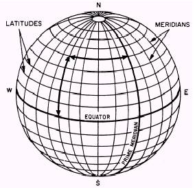
Systems One of the oldest reference systems is based upon the geographic coordinates-meridians and parallels. MERIDIANS are great circles of north-south rings crossing the equator at right angles and converging at the North and South Poles. (See fig. 5-2.) One meridian that runs through Greenwich, England, is known as the prime meridian. Meridians are used to measure LONGITUDE-the distance of a point east or west of the prime meridian. PARALLELS are great circles of
Figure 5-2.-Reference lines. Figure
5-3.-Position location. east-west rings running parallel to the equator. (See figs. 5-2 and 5-3.) Parallels are used to measure LATITUDE-the distance of a point north or south of the equator. Using meridians and parallels, you can locate any point on the surface of the earth. Geographic coordinates are expressed in angular measurement. The earth is divided into 360 degrees; each degree into 60 minutes; and each minute into 60 seconds. The degree is symbolized by ; the minute by; and the second by. Starting with 0 at the equator, the parallels of latitude are numbered to 90 both north and south. The extremities are the North Pole at 90 north latitude and the South Pole at 90 south latitude. Latitude can have the same numerical value north or south of the equator, so the direction N or S must always be given. Starting with 0 at the prime meridian, longitude is measured both east and west around the world. Lines east of the prime meridian are numbered from 0 to 180 and are identified as east longitude. Lines west of the prime meridian are numbered 0 to 180 and are identified as west longitude. The direction E or W must always be given to longitude. The line directly opposite the prime meridian, 180, may be referred to as either east or west longitude. Grids Military maps are divided into grids to provide a uniform system for referencing and making
Figure
5-4.-Grid system. measurements. Military grids consist of two sets of equally spaced parallel, straight lines intersecting at right angles and forming a series of squares. Each grid line is an even interval of the selected measurement unit, such as yards or meters. A portion of a military grid, or map, is shown in figure 5-1. The dimensions and orientation of different types of grids vary, but all military grids have three things in common: 1. They are all true rectangular grids. 2. They are superimposed; that is, drawn on top of the geographic projection. 3. They permit linear and angular measurements. The regularly spaced lines that make up the grids on any large-scale map are divisions of the 100 000-meters square; the lines are spaced at 10 000- or 1000-meter intervals. Each of these lines is labeled at both ends with a number showing its relation to the origin of the zone. For the 1000-meter grid, except for the numbers labeling the first grid line in each direction from the southwest corner of the sheet, the last three digits (000) of the number are omitted. (See fig. 5-1.) Two digits of the numbers are printed in large type, and the same two digits appear at intervals along the grid line on the face of the map. They are called the PRINCIPAL DIGITS and represent the 10,000 and 1,000 digits of the grid number; they are of major importance to the map reader because they are numbers he uses most often for referencing points. The smaller digits complete the COORDINATES of the grid lines, but they are rarely used for point designation. On sheets with grid line spacing at 10000 meters, only one principal digit is shown, representing the 10,000 digit of the grid number.
Figure 5-5.-Grid square, close-up. The designation of a point is based on the military principle of "Read RIGHT then UP." The precision desired determines the number of digits to be read beyond the principal digits. Remember that the term grid coordinate often indicates both the 100 000- meters-square identification and the desired number of digits. In many instances, it is a tactical requirement that the 100 000-meters-square identification be included in any point designation. Figure 5-4 shows a section of a simple grid system. Each line is numbered, starting at the lower left-hand corner, reading to the right and up. Remember, when you read a military map, you should always read from left to right and from bottom to top. Three squares in figure 5-4 have numbers in them to identify that particular grid square. The letter X has been placed in grid square 6937. To locate this point more precisely, see figure 5-5. You can see that the sides of the grid square have been divided into ten parts. This can be done by eye or with a scale. As shown in this figure, the X is located at coordinate 697373. The grid coordinates are written as one number but always contain an even number of digits. Examples are 6937 and 697373. |
||
|
||