| Tweet |

Custom Search
|
|
 
|
||
|
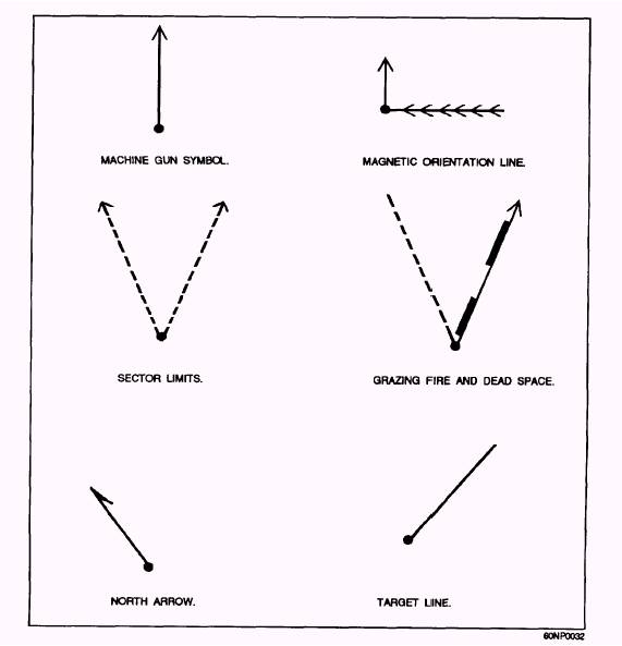
COMPLETING A RANGE CARD Range cards must be neat, clear, and prepared using a universal format. Observe the range card symbols and sample range card shown in figures 4-17 and 4-18 as each component is explained below. (see appendix II)
Figure 4-17.- Range card symbols. 1. Identification Block: This block identifies 4. Magnetic Orientation Line and Location what gun the card was drawn for and on what date it was drawn. For security reasons, the unit should only be identified to company level. 2. Weapon Symbol: The correct symbol for a machine gun is a single dot with a solid arrow extending out in the direction of the FPL or PDF. The dot represents the location of the gun. Record the magnetic azimuth of the FPL or PDF along this line. 3. Magnetic North Arrow: This arrow is drawn from the dot that represents the gun position in the direction that represents North from the gun position if you were looking out toward your sector of fire. The correct symbol for North is au arrow with a single barb. Grid Coordinates: These are the two methods used so that the CP, the battalion, or other units can positively locate a gun position. The magnetic orientation line method is a line drawn from a prominent terrain feature that is located preferably behind friendly lines. It is a single-solid line drawn from a prominent terrain feature to the gun position with several arrow heads pointing in the direction of the gun position; the magnetic azimuth in roils from the prominent terrain feature to the gun position is recorded on the line. NOTE: One degree is equal to 17.7778 mils. Example: To convert an azimuth of 140 degrees,
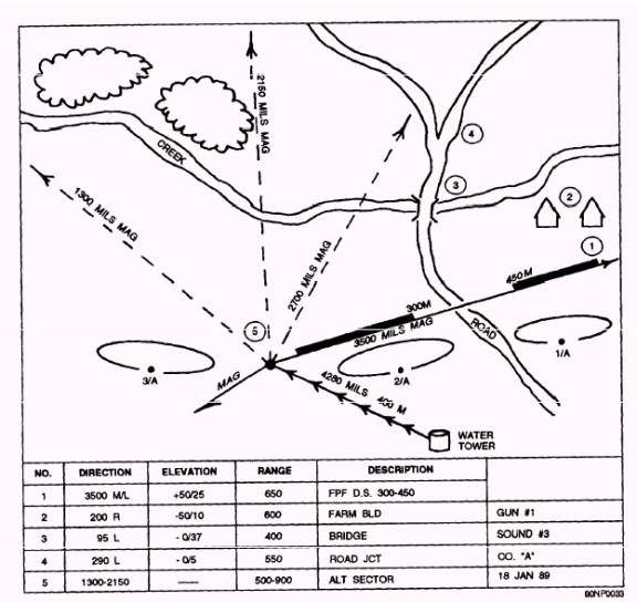
Figure 4-18.- Range card with an FPL. simply multiply 140 by 17.7778 which equals areas. Record the near and far limits of the dead space 2488.892. Round up to 2,489 mils. The grid coordinates method is where the grid of the gun position is recorded next to the dot in the machine gun symbol. Only one of these two methods to locate the position of the gun is needed. 5. Sector Limits: Sector limits are drawn as broken lines ending in arrow heads. When you are using an FPL, only one sector limit will be drawn because one is located in the same location as the FPL. 6. Grazing Fire: If an FPL is used, a heavy-shaded area is drawn along the inside of the FPL, which will show the limits of the grazing fire. Show any dead space by breaks in the grazing fire by shaded in meters or record the range next to the ends of the shaded areas. 7. Terrain Features: Draw only those terrain features that significantly add to the clarity of the range card. If a terrain feature is drawn, draw it to the correct perspective. 8. Location of Friendly Troops/ Equipment: Draw in any friendly positions or equipment that is either in or near the sector limits of the machine gun. Clearly label them with both a description, range, and direction. 9. Targets: Draw targets to perspective and label them with a number. The number one target will be either the FPL or the left sector limit. If the FPL is on the right sector limit, number all other targets sequentially from right to left; at all other times, number targets from left to right. There are two approved methods for recording target data. One method is to record data directly on the sketch along the line leading to the target. Another method is to use a data block at the bottom or reverse side of the range card. Range Card for an FPL The following scenario is to illustrate how a range card is prepared for an FPL.
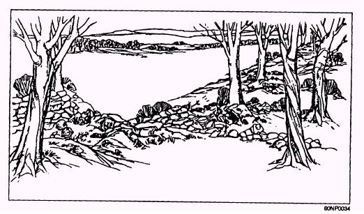
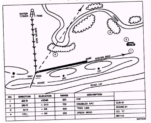
Figure 4-19 provides an illustration of a tactical field setting to help you. Scenario A machine gun fire team from the weapons platoon is attached to the second platoon of Charlie Company deployed along a low ridge overlooking a narrow valley. The weapons platoon squad leader, along with the other gun team, is supporting another company. The creek bottom across the valley is suspected of being a major infiltration route for the enemy. On the second platoon's right limit is the first platoon. Bravo Company joins the second platoon on the left limit. The second platoon commander has informed the machine gun team leader that the gun is to be positioned on the left flank of the platoon. The team leader informs the machine gun team to lay the gun to be able to fire an FPF across the front of the ridge. The line formed by the base of the ridge is to be the right sector limit. The trees at the bend in the creek in front of the gun position is the left limit. Interlocking fire for the FPF will be obtained from the third squad gun team attached to the first platoon. Using a compass or GPS, the gun team has located the gun at grid coordinate 94576259. The grid is also 750 meters from the water tower that is located on a magnetic back azimuth of 5,980 mils. The FPL lies on a magnetic azimuth of 4,250 mils.
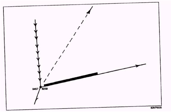
Figure 4-20 shows the beginning stages of the range card. It shows the weapon symbol, the magnetic North arrow, the magnetic orientation line and location grid coordinates, the sector limits, and the grazing fire.
Figure 4-21 shows the completed range card. Details have been added, such as the unit identification block, the terrain features, the location of friendly troops or equipment, and the targets with their individual data.
|
||
|
||