Custom Search
|
|
 
|
||
|
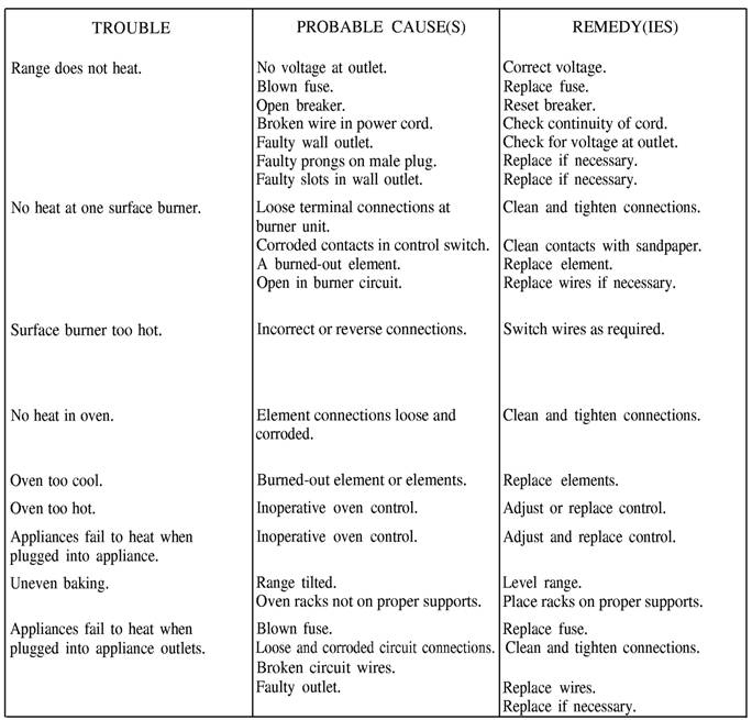
ELECTRICAL DIAGRAMS The majority of imaging equipment is operated by electricity. To troubleshoot and perform maintenance on this equipment adequately, you must have a basic knowledge of electricity and be able to read electrical diagrams. You should spend a few moments studying Table All-1.-Trouble-Shooting Table for Electric Ranges
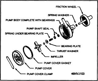
the circuit diagrams before you begin troubleshooting; this simplifies the task of isolating the trouble. When a circuit fails to function, you should use the logic diagram approach to locate the fault. The trial-and-error method of locating the fault(s) in a circuit is inefficient and time-consuming. If you have not been trained in electricity, you should read the Navy Electricity and Electronics Training Series (NEETS) Modules, particularly modules 2, 3, and 4. If you already possess knowledge about reading diagrams, the NEETS Modules can help you "get up to speed." Once you understand electrical diagrams, know prescribed maintenance and trouble-shooting procedures, and can use a voltmeter, you should be able to analyze and locate most of the faulty electrical components in imaging equipment. When working with electricity, Sailors commonly refer to all electrical diagrams as "schematics." This, however, is not correct. A schematic is a specific type of diagram with characteristics of its own and with a specific purpose. Each of the different diagrams has a specific purpose and has distinguishable features that set it apart from the others. These diagrams may be used to do the following: learn the operation of a specific system locate the components of a system identify the components of a system trace a circuit troubleshoot equipment repair equipment Pictorial Diagram The simplest of all diagrams is the pictorial diagram. The pictorial diagram is a picture or sketch of the components of a specific system and the wiring between these components. This simplified diagram identifies components, even if you are not familiar with their appearance. This type of diagram does not show physical locations of components or the manner in which the wiring is marked or routed. It does, however, show you the sequence in which the components are connected (fig. All-1). After studying the pictorial diagram, you should recognize the components and how they are connected to one another.
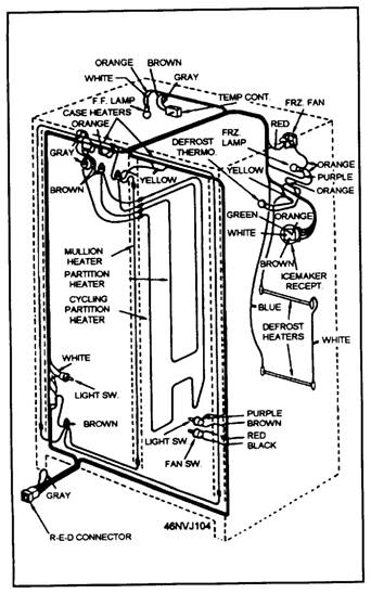
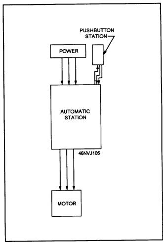
Figure AII-1-Pictorial diagram of a pump assembly. Isometric Diagram The purpose of an isometric diagram is to help you locate a component within a system. This type of diagram shows you the outline of a processor, printer, or other piece of equipment. Within the outline, the various components of a system are drawn in their respective (or relative) locations. The isometric diagram also shows interconnecting cables running between components (fig. All-2). Block Diagram A block diagram (fig. All-3) presents a general description of a system and its functions. This type of diagram is often used with accompanying text material. A block diagram shows the major components of a system and the interconnections of these components. All components are shown in block form and each block is labeled for identification purposes. Single-Line Diagram The single-line diagram (fig. AII-4) is used basically for the same purpose as the block diagram. When the single-line diagram is used with text material, it provides you with a basic understanding of the components and their functions in a system. There are two major differences between the single-line diagram and the block diagram. The first difference is that the single-line diagram uses symbols, rather than labeled blocks, to represent components. Second, the single-line diagram is just that-all components are shown in a single line. There are no
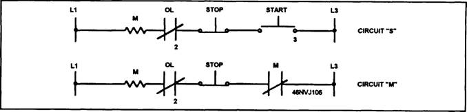
Figure AII-2.-Isometric wiring diagram of a refrigerator. interconnections for selected components in a single-line diagram, as there are in a block diagram. The single-line diagram is a simplified type of diagram and should be used primarily to understand, in broad terms, the function of each of the various components in the total system. Schematic Diagram A schematic diagram (fig. All-5) uses graphic symbols to show both the electrical components and the functional organization of a circuit. You can use the schematic diagram to trace a circuit and its functions without regard to the actual physical size, shape, or location of the component devices or parts. A schematic diagram is most useful for learning the overall operation of a system.
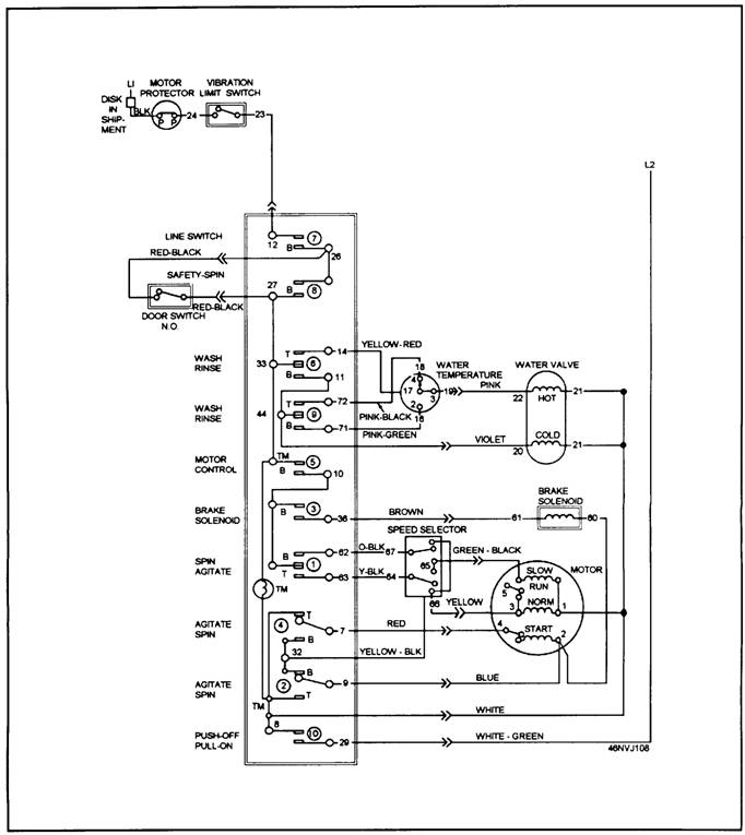
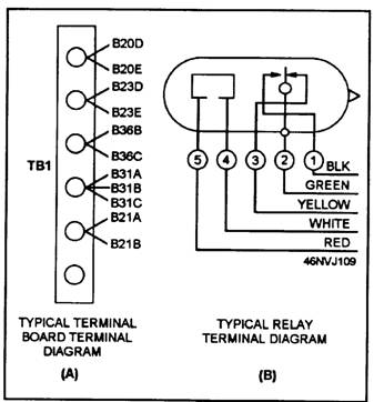
Figure All-3-Block diagram. Wiring Diagram A wiring diagram (fig. All-6) is a detailed diagram of each circuit installation showing all of the wiring, connectors, terminal boards, and electrical or electronic components of the circuit. It also identifies wire by wire number or color code. Wiring diagrams are used to troubleshoot and repair electrical or electronic circuits. The schematic diagram discussed previously should be used to determine the location where the trouble in the circuit could be when a malfunction occurs. However, the schematic diagram does not show the terminals, connector points, and so on, in the circuit. Therefore, you must use the circuit wiring diagram to determine where to make the voltage or resistance checks in the circuit. Terminal Diagram A terminal diagram is useful when connecting wires to terminal boards, relays, switches, and other
Figure AII-4.-Single-line diagram of a motor control circuit.
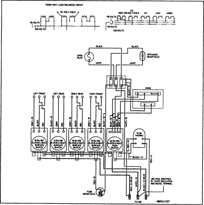
Figure AII-5.-Schematic diagram of an electric range.
Figure All-6.-Wiring diagram of a washing machine.
Figure All-7-Terminal diagram. components of a circuit. Figure All-7 shows two typical terminal diagrams: (A) shows the wire numbers connected to each terminal of a terminal board and (B) shows the color codes of the wires that are connected to a relay. This has been a brief overview of trouble-shooting procedures and the use and interpretation of the various electrical diagrams. The diagrams discussed were selected because of their simplicity and ease of interpretation. Many diagrams you will encounter are far more complex. Begin with the simpler diagrams. Your proficiency in using the more complex diagrams will increase with experience. |
 |
|
|
||