Custom Search
|
|
  |
|
|
SHUNT MOTOR
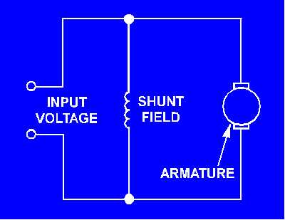
A shunt motor is connected in the same way as a shunt generator. The field windings are connected in parallel (shunt) with the armature windings. The circuit for a shunt motor is shown in figure 2-4. Figure 2-4. - Shunt-wound dc motor.
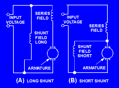
Once you adjust the speed of a dc shunt motor, the speed remains relatively constant even under changing load conditions. One reason for this is that the field flux remains constant. A constant voltage across the field makes the field independent of variations in the armature circuit. If the load on the motor is increased, the motor tends to slow down. When this happens, the counter emf generated in the armature decreases. This causes a corresponding decrease in the opposition to battery current flow through the armature. Armature current increases, causing the motor to speed up. The conditions that established the original speed are reestablished, and the original speed is maintained. Conversely, if the motor load is decreased, the motor tends to increase speed; counter emf increases, armature current decreases, and the speed decreases. In each case, all of this happens so rapidly that any actual change in speed is slight. There is instantaneous tendency to change rather than a large fluctuation in speed. Q.9 What advantage does a shunt motor have over a series motor? COMPOUND MOTOR A compound motor has two field windings, as shown in figure 2-5. One is a shunt field connected in parallel with the armature; the other is a series field that is connected in series with the armature. The shunt field gives this type of motor the constant speed advantage of a regular shunt motor. The series field gives it the advantage of being able to develop a large torque when the motor is started under a heavy load. It should not be a surprise that the compound motor has both shunt- and series-motor characteristics. Figure 2-5. - Compound-wound dc motor.
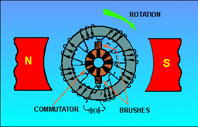
When the shunt field is connected in parallel with the series field and armature, it is called a "long shunt" as shown in figure 2-5, (view A). Otherwise, it is called a "short shunt", as shown in figure 2-5, (view B). TYPES OF ARMATURES As with dc generators, dc motors can be constructed using one of two types of armatures. A brief review of the Gramme-ring and drum-wound armatures is necessary to emphasize the similarities between dc generators and dc motors. GRAMME-RING ARMATURE The Gramme-ring armature is constructed by winding an insulated wire around a soft-iron ring (fig. 2-6). Eight equally spaced connections are made to the winding. Each of these is connected to a commutator segment. The brushes touch only the top and bottom segments. There are two parallel paths for current to follow - one up the left side and one up the right side. These paths are completed through the top brush back to the positive lead of the battery. Figure 2-6. - Gramme-ring armature.
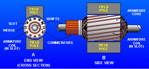
To check the direction of rotation of this armature, you should use the right-hand rule for motors. Hold your thumb, forefinger, and middle finger at right angles. Point your forefinger in the direction of field flux; in this case, from left to right. Now turn your wrist so that your middle finger points in the direction that the current flows in the winding on the outside of the ring. Note that current flows into the page (away from you) in the left-hand windings and out of the page (toward you) in the right-hand windings. Your thumb now points in the direction that the winding will move. The Gramme-ring armature is seldom used in modem dc motors. The windings on the inside of the ring are shielded from magnetic flux, which causes this type of armature to be inefficient. The Gramme-ring armature is discussed primarily to help you better understand the drum-wound armature. DRUM-WOUND ARMATURE The drum-wound armature is generally used in ac motors. It is identical to the drum winding discussed in the chapter on dc generators. If the drum-wound armature were cut in half, an end view at the cut would resemble the drawing in figure 2-7, (view A),Figure 2-7, (view B) is a side view of the armature and pole pieces. Notice that the length of each conductor is positioned parallel to the faces of the pole pieces. Therefore, each conductor of the armature can cut the maximum flux of the motor field. The inefficiency of the Gramme-ring armature is overcome by this positioning. Figure 2-7. - Drum-type armature.
The direction of current flow is marked in each conductor in figure 2-7, (view A) as though the armature were turning in a magnetic field. The dots show that current is flowing toward you on the left side, and the crosses show that the current is flowing away from you on the right side. Strips of insulation are inserted in the slots to keep windings in place when the armature spins. These are shown as wedges in figure 2-7, (view A). Q.10 Why is the Gramme-ring armature not more widely used? |
 |
|
|
Integrated Publishing, Inc. - A (SDVOSB) Service Disabled Veteran Owned Small Business
|