Custom Search
|
|
  |
|
|
Hysteresis Losses
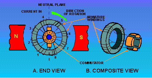
Hysteresis loss is a heat loss caused by the magnetic properties of the armature. When an armature core is in a magnetic field, the magnetic particles of the core tend to line up with the magnetic field. When the armature core is rotating, its magnetic field keeps changing direction. The continuous movement of the magnetic particles, as they try to align themselves with the magnetic field, produces molecular friction. This, in turn, produces heat. This heat is transmitted to the armature windings. The heat causes armature resistances to increase. To compensate for hysteresis losses, heat-treated silicon steel laminations are used in most dc generator armatures. After the steel has been formed to the proper shape, the laminations are heated and allowed to cool. This annealing process reduces the hysteresis loss to a low value. The actual construction and operation of a practical dc generator differs somewhat from our elementary generators. The differences are in the construction of the armature, the manner in which the armature is wound, and the method of developing the main field. A generator that has only one or two armature loops has high ripple voltage. This results in too little current to be of any practical use. To increase the amount of current output, a number of loops of wire are used. These additional loops do away with most of the ripple. The loops of wire, called windings, are evenly spaced around the armature so that the distance between each winding is the same. The commutator in a practical generator is also different. It has several segments instead of two or four, as in our elementary generators. The number of segments must equal the number of armature coils. GRAMME-RING ARMATURE The diagram of a GRAMME-RING armature is shown in figure 1-12, view A. Each coil is connected to two commutator segments as shown. One end of coil 1 goes to segment A, and the other end of coil 1 goes to segment B. One end of coil 2 goes to segment C, and the other end of coil 2 goes to segment B. The rest of the coils are connected in a like manner, in series, around the armature. To complete the series arrangement, coil 8 connects to segment A. Therefore, each coil is in series with every other coil. Figure 1-12. - Gramme-ring armature.
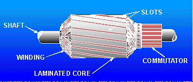
Figure 1-12, view B shows a composite view of a Gramme-ring armature. It illustrates more graphically the physical relationship of the coils and commutator locations. The windings of a Gramme-ring armature are placed on an iron ring. A disadvantage of this arrangement is that the windings located on the inner side of the iron ring cut few lines of flux. Therefore, they have little, if any, voltage induced in them. For this reason, the Gramme-ring armature is not widely used. DRUM-TYPE ARMATURE A drum-type armature is shown in figure 1-13.The armature windings are placed in slots cut in a drum-shaped iron core. Each winding completely surrounds the core so that the entire length of the conductor cuts the main magnetic field. Therefore, the total voltage induced in the armature is greater than in the Gramme-ring. You can see that the drum-type armature is much more efficient than the Gramme-ring. This accounts for the almost universal use of the drum-type armature in modem dc generators. Figure 1-13. - Drum-type armature.
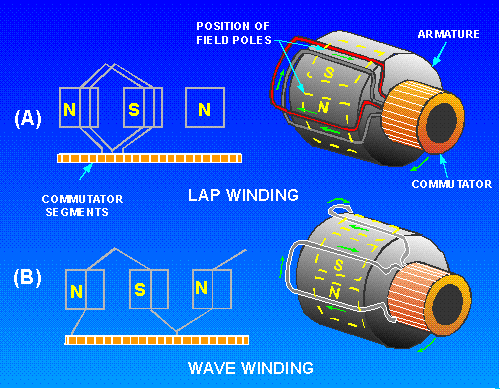
Drum-type armatures are wound with either of two types of windings - the LAP WINDING or the WAVE WINDING. The lap winding is illustrated in figure 1-14, view A This type of winding is used in dc generators designed for high-current applications. The windings are connected to provide several parallel paths for current in the armature. For this reason, lap-wound armatures used in dc generators require several pairs of poles and brushes. Figure 1-14. - Types of windings used on drum-type armatures.
Figure 1-14, view B, shows a wave winding on a drum-type armature. This type of winding is used in dc generators employed in high-voltage applications. Notice that the two ends of each coil are connected to commutator segments separated by the distance between poles. This configuration allows the series addition of the voltages in all the windings between brushes. This type of winding only requires one pair of brushes. In practice, a practical generator may have several pairs to improve commutation. Q.16 Why are drum-type armatures preferred over the Gramme-ring armature in modern dc
generators? |
 |
|
|
Integrated Publishing, Inc. - A (SDVOSB) Service Disabled Veteran Owned Small Business
|