Custom Search
|
|
  |
|
|
OHMMETER SAFETY PRECAUTIONS The following safety precautions and operating procedures for ohmmeters are the MINIMUM necessary to prevent injury and damage.
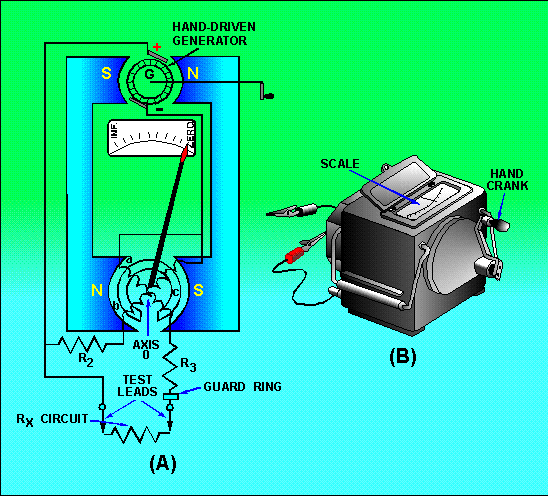
An ordinary ohmmeter cannot be used for measuring resistance of multimillions of ohms, such as in conductor insulation. To adequately test for insulation break down, it is necessary to use a much higher potential than is furnished by the battery of an ohmmeter. This potential is placed between the conductor and the outside surface of the insulation. An instrument called a MEGOHMMETER (MEGGER) is used for these tests. The megger (fig. 1-36)is a portable instrument consisting of two primary elements: (1) a hand-driven dc generator, G, which supplies the high voltage for making the measurement, and (2) the instrument portion, which indicates the value of the resistance being measured. The instrument portion is of the opposed-coil type, as shown in figure 1-36(A). Coils a and b are mounted on the movable member c with a fixed relationship to each other, and are free to turn as a unit in a magnetic field. Coil b tends to move the pointer counterclockwise, and coil a tends to move the pointer clockwise. Figure 1-36. - A megger internal circuit;
Coil a is connected in series with R3 and the unknown resistance, Rx, to be measured. The combination of coil, R3, and Rx forms a direct series path between the positive (+) and negative (-) brushes of the dc generator. Coil b is connected in series with R2 and this combination is also connected across the generator. There are no restraining springs on the movable member of the instrument portion of the megger. Therefore, when the generator is not operated, the pointer floats freely and may come to rest at any position on the scale.
The guard ring intercepts leakage current. Any leakage currents intercepted are shunted to the negative side of the generator. They do not flow through coil a; therefore, they do not affect the meter reading. If the test leads are open-circuited, no current flows in coil a. However, current flows internally through coil b, and deflects the pointer to infinity, which indicates a resistance too large to measure. When a resistance such as Rx is connected between the test leads, current also flows in coil a, tending to move the pointer clockwise. At the same time, coil b still tends to move the pointer counterclockwise. Therefore, the moving element, composed of both coils and the pointer, comes to rest in a position at which the two forces are balanced. This position depends upon the value of the external resistance, which controls the relative amount of current in coil a. Because changes in voltage affect both coil a and coil b in the same proportion, the position of the moving system is independent of the voltage. If the test leads are short-circuited, the pointer rests at zero because the current in coil a is relatively large. The instrument is not damaged under these circumstances because the current is limited by R3. The external view of one type of megger is shown in figure 1-36(B). Navy meggers are usually rated at 500 volts. To avoid excessive test voltages, most meggers are equipped with friction clutches. When the generator is cranked faster than its rated speed, the clutch slips and the generator speed and output voltage are not permitted to exceed their rated values. When extremely high resistances-for example, 10,000 megohms or more-are to be measured, a high voltage is needed to cause sufficient current flow to actuate the meter movement. For extended ranges, a 1,000-volt generator is available. When a megger is used, the generator voltage is present on the test leads. This voltage could be hazardous to you or to the equipment you are checking. Therefore, NEVER TOUCH THE TEST LEADS WHILE THE MEGGER IS BEING USED and isolate the item you are checking from the equipment before using the megger. Using the Megger To use a megger to check wiring insulation, connect one test lead to the insulation and the other test lead to the conductor, after isolating the wiring from the equipment. Turn the hand crank until the slip clutch just begins to slip and note the meter reading. Normal insulations should read infinity. Any small resistance reading indicates the insulation is breaking down. Megger Safety Precautions When you use a megger, you could be injured or damage equipment you are working on if the following MINIMUM safety precautions are not observed. Use meggers on high-resistance measurements only (such as insulation measurements or to check two separate conductors on a cable).
Q.49 What is the primary use of a megger? |
|
|
|
Integrated Publishing, Inc. - A (SDVOSB) Service Disabled Veteran Owned Small Business
|