Custom Search
|
|
  |
|
|
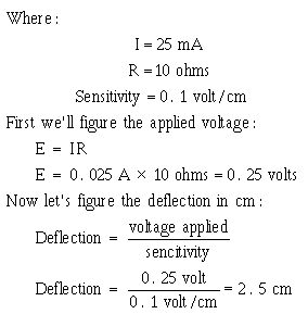
OSCILLOSCOPE METHOD Current can be measured with an oscilloscope by shunting the input terminals with a low-value resistor. The input terminals must then be connected in series with the circuit being tested. The value of the resistor must be small enough not to interfere with the operation of the circuit under test. At the same time, it must be large enough that the voltage developed will cause adequate deflection of the oscilloscope trace. For example, if an oscilloscope with a vertical deflection sensitivity of 0.1 volt rms per centimeter (cm) is used in conjunction with a 10-ohm shunt resistor to measure a 25-milliamp current, the vertical trace will be deflected 2.5 centimeters, as shown in the following example:
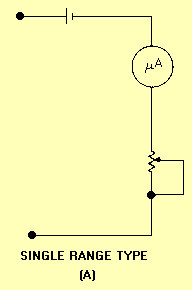
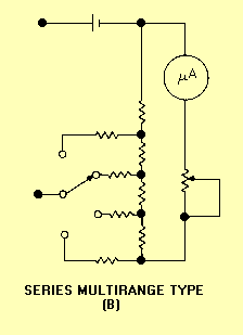
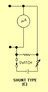
For current measurements the oscilloscope can be calibrated by connecting an ammeter in series with the input terminals and the calibration signal source. An alternate method is to determine the value of the shunt resistor and measure the calibration signal voltage developed across it with an accurate voltmeter. The calibration signal current can then be calculated by means of Ohm's law. Since the oscilloscope merely indicates the voltage developed across the shunt resistor, the measurements for alternating or direct current will be similar to voltage measurements using an oscilloscope. RESISTANCE MEASUREMENTS A high percentage of technical manuals contain point-to-point resistance charts that list correct resistance readings for major test points. These resistance charts are extremely useful when you troubleshoot faulty equipment. Without them, equipment resistance measurements within a complicated circuit would not mean much. Many circuits contain other circuit elements, such as capacitors, coils, or other resistors in parallel with the resistances being measured. This, of course, is a possible source of measurement error that you eliminate when you disconnect or unsolder one side of the resistor or a group of resistors under test. You should be thoroughly familiar with the calibration of your ohmmeter. Analog meters are typically more accurate and easier to read at midscale. With the exception of bridge circuits, a meter may provide only approximate resistance readings. However, these readings may be adequate when you also consider the wide tolerances of resistors themselves. An ohmmeter that you use in field testing should be portable, convenient, and simple to operate - factors that usually are more important than extreme accuracy. When an ohmmeter is used, completely de-energize the circuit under test and remove any current-sensitive elements before the resistance measurement is performed. Low-resistance measurements that require precision readings should be taken with a bridge type of instrument. An ohmmeter consists of a galvanometer, batteries, and resistors of known value that are connected in such a way that unknown resistors to be measured are compared with standard values. Figure 1-10 illustrates three basic ohmmeter circuits: (A) single range type, (B) series multirange type, and (C) shunt type. Figure 1-10A. - Basic ohmmeter circuits.
Figure 1-10B. - Basic ohmmeter circuits.
Figure 1-10C. - Basic ohmmeter circuits.
When you use an analog multimeter to perform resistance measurements, the first thing you do is zero the meter. The meter indication varies greatly depending on the resistance of the test leads, the condition of the batteries within the meter, and the resistance range selected on the multimeter. The meter should be zeroed every time you change range settings. To zero a multimeter you short the leads together and adjust the meter for a full-scale deflection. Scale markings are spaced closer together toward the infinity point on the meter; therefore, more accurate readings are obtained near center scale. You should select a range setting that will give you a mid-scale indication. Ohmmeter applications include resistance measurements; continuity checks; and inductor, capacitor, and transformer checks. A transformer, for example, may be tested by checking whether there is an open or short, low-insulation resistance to ground, or improper continuity between transformer windings. A capacitor may be tested to determine whether it is open or shorted. Ensure that capacitors are properly discharged before you test them; otherwise, damage to the multimeter may occur. When an ohmmeter is placed in series with a capacitor, the changing current will cause a meter deflection that is proportional to the capacitance. The deflection obtained is compared with the deflection from a similar capacitor of known value. This deflection may be small or large, depending on the type and size of the capacitor and the voltage of the battery within the meter. An external series battery will increase the sensitivity of the instrument. Q.10 How do you compensate for the resistance of the test leads of a meter? DIGITAL MULTIMETER The two major advantages of using a digital multimeter are its ease of operation and accuracy. Most digital multimeters can be ordered with an optional battery pack, which makes them just as portable as an analog multimeter. Another advantage is that their LED or LCD readouts are much easier to read than the scale on an analog multimeter. Digital multimeters also are ideally suited for measuring sensitive devices that might otherwise be damaged by the excessive current associated with analog multimeters - maximum current flow through the component being tested is typically limited to less than 1 milliamp. When measuring small values of resistances, remember to consider the resistance of your test leads. Most digital multimeters cannot be zeroed in the way analog multimeters can. With digital multimeters, you have to short the leads, read the lead resistance displayed, and then subtract the reading from subsequent component measurements that you make. Q.11 Why are digital multimeters well suited for testing sensitive devices? |
 |