Custom Search
|
|
  |
|||||||||||||||||||||||||||||||||||||||||||||||||
|
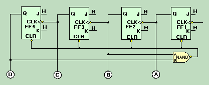
Decade Counter A decade counter is a binary counter that is designed to count to 1010, or 10102. An ordinary four-stage counter can be easily modified to a decade counter by adding a NAND gate as shown in figure 3-25. Notice that FF2 and FF4 provide the inputs to the NAND gate. The NAND gate outputs are connected to the CLR input of each of the FFs. Figure 3-25. - Decade counter.
The counter operates as a normal counter until it reaches a count of 10102, or 1010. At that time, both inputs to the NAND gate are HIGH, and the output goes LOW. This LOW applied to the CLR input of the FFs causes them to reset to 0. Remember from the discussion of J-K FFs that CLR and PS or PR override any existing condition of the FF. Once the FFs are reset, the count may begin again. The following table shows the binary count and the inputs and outputs of the NAND gate for each count of the decade counter:
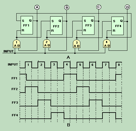
Changing the inputs to the NAND gate can cause the maximum count to be changed. For instance, if FF4 and FF3 were wired to the NAND gate, the counter would count to 11002 (1210), and then reset. Q.43 How many stages are required for a decade counter? Ring Counter A ring counter is defined as a loop of bistable devices (flip-flops) interconnected in such a manner that only one of the devices may be in a specified state at one time. If the specified condition is HIGH, then only one device may be HIGH at one time. As the clock, or input, signal is received, the specified state will shift to the next device at a rate of 1 shift per clock, or input, pulse. Figure 3-26, view A, shows a typical four-stage ring counter. This particular counter is composed of R-S FFs. J-K FFs may be used as well. Notice that the output of each AND gate is input to the R, or reset side, of the nearest FF and to the S, or set side, of the next FF. The Q output of each FF is applied to the B input of the AND gate that is connected to its own R input. Figure 3-26. - Ring counter: A. Logic diagram; B. Timing diagram.
The circuit input may be normal CLK pulses or pulses from elsewhere in the equipment that would indicate some operation has been completed. Now, let's look at the circuit operation and observe the signal flow as shown in figure 3-26, view B. For an initial condition, let's assume that the output of FF1 is HIGH and that the input and FF2, FF3, and FF4 are LOW. Under these conditions, lamp A will be lit; and lamps B, C, and D will be extinguished. The HIGH from FF1 is also applied to the B input of AND gate 1. The first input pulse is applied to the A input of each of the AND gates. The B inputs to AND gates 2, 3, and 4 are LOW since the outputs of FF2, FF3, and FF4 are LOW. AND gate 1 now has HIGHs on both inputs and produces a HIGH output. This HIGH simultaneously resets FF1 and sets FF2. Lamp A then goes out, and lamp B goes on. We now have a HIGH on AND gate 2 at the B input. We also have a LOW on AND gate 1 at input B. Input pulse 2 will produce a HIGH output from AND gate 2 since AND gate 2 is the only one with HIGHs on both inputs. The HIGH from AND gate 2 causes FF2 to reset and FF3 to set. Indicator B goes out and C goes on. Pulse 3 will cause AND gate 3 to go HIGH. This results in FF3 being reset and FF4 being set. Pulse 4 causes FF4 to reset and FF1 to set, bringing the counter full circle to the initial conditions. As long as the counter is operational, it will continue to light the lamps in sequence - 1, 2, 3, 4; 1, 2, 3, 4, etc. As we stated at the beginning of this section, only one FF may be in the specified condition at one time. The specified condition shifts one position with each input pulse. Q.45 In figure 3-26, view A, which AND gate causes FF3 to set? |
 |
||||||||||||||||||||||||||||||||||||||||||||||||
|
|
Integrated Publishing, Inc. - A (SDVOSB) Service Disabled Veteran Owned Small Business
|