Custom Search
|
|
  |
|
|
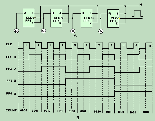
COUNTERS A counter is simply a device that counts. Counters may be used to count operations, quantities, or periods of time. They may also be used for dividing frequencies, for addressing information in storage, or for temporary storage. Counters are a series of FFs wired together to perform the type of counting desired. They will count up or down by ones, twos, or more. The total number of counts or stable states a counter can indicate is called MODULUS. For instance, the modulus of a four-stage counter would be 1610, since it is capable of indicating 00002 to 11112. The term modulo is used to describe the count capability of counters; that is, modulo-16 for a four-stage binary counter, modulo-11 for a decade counter, modulo-8 for a three-stage binary counter, and so forth. Ripple Counters Ripple counters are so named because the count is like a chain reaction that ripples through the counter because of the time involved. This effect will become more evident with the explanation of the following circuit. Figure 3-23, view A, shows a basic four-stage, or modulo-16, ripple counter. The inputs and outputs are shown in view B. The four J-K FFs are connected to perform a toggle function; which, you will recall, divides the input by 2. The HIGHs on the J and K inputs enable the FFs to toggle. The inverters on the clock inputs indicate that the FFs change state on the negative-going pulse. Figure 3-23. - Four-stage ripple counter: A. Logic diagram; B. Timing diagram.
Assume that A, B, C, and D are lamps and that all the FFs are reset. The lamps will all be out, and the count indicated will be 00002. The negative-going pulse of clock pulse 1 causes FF1 to set. This lights lamp A, and we have a count of 00012. The negative-going pulse of clock pulse 2 toggles FF1, causing it to reset. This negative-going input to FF2 causes it to set and causes B to light. The count after two clock pulses is 00102, or 210. Clock pulse 3 causes FF1 to set and lights lamp A. The setting of FF1 does not affect FF2, and lamp B stays lit. After three clock pulses, the indicated count is 00112. Clock pulse 4 causes FF1 to reset, which causes FF2 to reset, which causes FF3 to set, giving us a count of 01002. This step shows the ripple effect. This setting and resetting of the FFs will continue until all the FFs are set and all the lamps are lit. At that time the count will be 11112 or 1510. Clock pulse 16 will cause FF1 to reset and lamp A to go out. This will cause FF2 through FF4 to reset, in order, and will extinguish lamps B, C, and D. The counter would then start at 00012 on clock pulse 17. To display a count of 1610 or 100002, we would need to add another FF. The ripple counter is also called an ASYNCHRONOUS counter. Asynchronous means that the events (setting and resetting of FFs) occur one after the other rather than all at once. Because the ripple count is asynchronous, it can produce erroneous indications when the clock speed is high. A high-speed clock can cause the lower stage FFs to change state before the upper stages have reacted to the previous clock pulse. The errors are produced by the FFs' inability to keep up with the clock. Synchronous Counter High-frequency operations require that all the FFs of a counter be triggered at the same time to prevent errors. We use a SYNCHRONOUS counter for this type of operation. The synchronous counter is similar to a ripple counter with two exceptions: The clock pulses are applied to each FF, and additional gates are added to ensure that the FFs toggle in the proper sequence. A logic diagram of a three-state (modulo-8) synchronous counter is shown in figure 3-24, view A. The clock input is wired to each of the FFs to prevent possible errors in the count. A HIGH is wired to the J and K inputs of FF1 to make the FF toggle. The output of FF1 is wired to the J and K inputs of FF2, one input of the AND gate, and indicator A. The output of FF2 is wired to the other input of the AND gate and indicator B. The AND output is connected to the J and K inputs of FF3. The C indicator is the only output of FF3. Figure 3-24. - Three-stage synchronous counter: A. Logic diagram; B. Timing Diagram.
During the explanation of this circuit, you should follow the logic diagram, view A, and the pulse sequences, view B. Assume the following initial conditions: The outputs of all FFs, the clock, and the AND gate are 0; the J and K inputs to FF1 are HIGH. The negative-going portion of the clock pulse will be used throughout the explanation. Clock pulse 1 causes FF1 to set. This HIGH lights lamp A, indicating a binary count of 001. The HIGH is also applied to the J and K inputs of FF2 and one input of the AND gate. Notice that FF2 and FF3 are unaffected by the first clock pulse because the J and K inputs were LOW when the clock pulse was applied. As clock pulse 2 goes LOW, FF1 resets, turning off lamp A. In turn, FF2 will set, lighting lamp B and showing a count of 0102. The HIGH from FF2 is also felt by the AND gate. The AND gate is not activated at this time because the signal from FF1 is now a LOW. A LOW is present on the J and K inputs of FF3, so it is not toggled by the clock. Clock pulse 3 toggles FF1 again and lights lamp A. Since the J and K inputs to FF2 were LOW when pulse 3 occurred, FF2 does not toggle but remains set. Lamps A and B are lit, indicating a count of 0112. With both FF1 and FF2 set, HIGHs are input to both inputs of the AND gate, resulting in HIGHs to J and K of FF3. No change occurred in the output of FF3 on clock pulse 3 because the J and K inputs were LOW at the time. Just before clock pulse 4 occurs, we have the following conditions: FF1 and FF2 are set, and the AND gate is outputting a HIGH to the J and K inputs of FF3. With these conditions all of the FFs will toggle with the next clock pulse. At clock pulse 4, FF1 and FF2 are reset, and FF3 sets. The output of the AND gate goes to 0, and we have a count of 1002. It appears that the clock pulse and the AND output both go to 0 at the same time, but the clock pulse arrives at FF3 before the AND gate goes LOW because of the transit time of the signal through FF1, FF2, and the AND gate. Between pulses 4 and 8, FF3 remains set because the J and K inputs are LOW. FF1 and FF2 toggle in the same sequence as they did on clock pulses 1, 2, and 3. Clock pulse 7 results in all of the FFs being set and the AND gate output being HIGH. Clock pulse 8 causes all the FFs to reset and all the lamps to turn off, indicating a count of 0002 . The next clock pulse (9) will restart the count sequence. Q.37 What is the modulus of a five-stage binary counter? |
|