Custom Search
|
|
  |
|
|
TOGGLE FLIP-FLOP The toggle, or T, flip-flop is a bistable device that changes state on command from a common input terminal. The standard symbol for a T FF is illustrated in figure 3-15, view A. The T input may be preceded by an inverter. An inverter indicates a FF will toggle on a HIGH-to-LOW transition of the input pulse. The absence of an inverter indicates the FF will toggle on a LOW-to-HIGH transition of the pulse. Figure 3-15. - Toggle (T) flip-flop: A. Standard symbol; B. Timing diagram.
The timing diagram in figure 3-15, view B, shows the toggle input and the resulting outputs. We will assume an initial condition (T0) of Q being LOW and Q being HIGH. At T1, the toggle changes from a LOW to a HIGH and the device changes state; Q goes HIGH and Q goes LOW. The outputs remain the same at T2since the device is switched only by a LOW-to-HIGH transition. At T3, when the toggle goes HIGH, Q goes LOW and Q goes HIGH; they remain that way until T5. Between T1 and T5, two complete cycles of T occur. During the same time period, only one cycle is observed for Q or Q. Since the output cycle is one-half the input cycle, this device can be used to divide the input by 2. The most commonly used T FFs are J-K FFs wired to perform a toggle function. This use will be demonstrated later in this section. Q.22 How many inputs does a T FF have? D FLIP-FLOP The D FF is a two-input FF. The inputs are the data (D) input and a clock (CLK) input. The clock is a timing pulse generated by the equipment to control operations. The D FF is used to store data at a predetermined time and hold it until it is needed. This circuit is sometimes called a delay FF. In other words, the data input is delayed up to one clock pulse before it is seen in the output. The simplest form of a D FF is shown in figure 3-16, view A. Now, follow the explanation of the circuit using the Truth Table and the timing diagram shown in figure 3-16, views B and C. Figure 3-16. - D flip-flop: A. Standard symbol; B. Truth Table; C. Timing diagram.
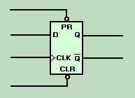
Depending on the circuit design, the clock (CLK) can be a square wave, a constant frequency, or asymmetrical pulses. In this example the clock (CLK) input will be a constant input at a given frequency. This frequency is determined by the control unit of the equipment. The data (D) input will be present when there is a need to store information. Notice in the Truth Table that output Q reflects the D input only when the clock transitions from 0 to 1 (LOW to HIGH). Let's assume that at T0, CLK is 0, D is 1, and Q is 0. Input D remains at 1 for approximately 2 1/2 clock pulses. At T1, when the clock goes to 1, Q also goes to 1 and remains at 1 even though D goes to 0 between T2 and T3. At T3, the positive-going pulse of the clock causes Q to go to 0, reflecting the condition of D. The positive-going clock pulse at T5 causes no change in the output because D is still LOW. Between T5 and T6, D goes HIGH, but Q remains LOW until T7 when the clock goes HIGH. The key to understanding the output of the D FF is to remember that the data (D) input is seen in the output only after the clock has gone HIGH. You may see D FF symbols with two additional inputs - CLR (clear) and PR (preset). These inputs are used to set the start condition of the FF - CLR sets Q to 0; PR sets Q to 1. Figure 3-17 shows the standard symbol with the CLR and PR inputs. Since these inputs are preceded by inverters (part of the FF), a LOW-going signal is necessary to activate the FF. These signals (CLR and PR) override any existing condition of the output. Figure 3-17. - D flip-flop with PR and CLR inputs.
You may also see an inverter at the clock input. In this case, the output will change on the negative-going transition of the clock pulse. Q.24 What are the inputs to a D FF? |
 |
|
|
Integrated Publishing, Inc. - A (SDVOSB) Service Disabled Veteran Owned Small Business
|