|
MULTIPLE-LOAD VOLTAGE DIVIDERS
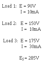
A multiple-load voltage divider is shown in figure 3-65. An important point that was not emphasized before is that when using the 10% rule-of-thumb to calculate the bleeder current, you must take 10% of the total load current.
Figure 3-65. - Multiple-load voltage divider.

Given the information shown in figure 3-65, you can calculate the values for the resistors needed in the voltage-divider circuits. The same steps will be followed as in the previous voltage divider problem.
Given:

The bleeder current should be 10% of the total load current.
Solution:

Since the voltage across R1 (ER1) is equal to the voltage requirement for load 1, Ohm's law can be used to calculate the value for R1.
Solution:

The current through R2 (IR2) is equal to the current through R1plus the current through load 1.
Solution:

The voltage across R2 (ER2) is equal to the difference between the voltage requirements of load 1 and load 2.

Ohm's law can now be used to solve for the value of R2.
Solution:

The current through R3 (IR3) is equal to the current through R2 plus the current through load 2.

The voltage across R3 (ER3) equals the difference between the voltage requirement of load 3 and load 2.

Ohm's law can now be used to solve for the value of R 3.
Solution:

The current through R4 (IR4) is equal to the current through R3 plus the current through load 3. IR4 is equal to total circuit current (I T).

The voltage across R4 (ER4) equals the difference between the source voltage and the voltage requirement of load 3.

Ohm's law can now be used to solve for the value of R 4.
Solution:

With the calculations just explained, the values of the resistors used in the voltage divider are as follows:

|


