|
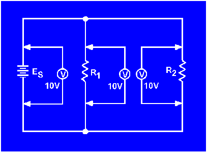
Voltage in a Parallel Circuit
You have seen that the source voltage in a series circuit divides proportionately across each resistor in the circuit. IN A PARALLEL CIRCUIT, THE SAME VOLTAGE IS PRESENT IN EACH BRANCH. (A branch is a section of a circuit that has a complete path for current.) In figure 3-37 this voltage is equal to the applied voltage (Es). This can be expressed in equation form as:
ES = ER1 = ER2
Voltage measurements taken across the resistors of a parallel circuit, as illustrated by figure 3-38 verify this equation. Each meter indicates the same amount of voltage. Notice that the voltage across each resistor is the same as the applied voltage.
Figure 3-38. - Voltage comparison in a parallel circuit.
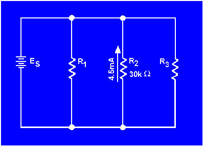
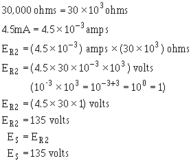
Example: Assume that the current through a resistor of a parallel circuit is known to be 4.5 milliamperes (4.5
mA) and the value of the resistor is 30,000 ohms (30 kΩ). Determine the source voltage. The circuit is shown in figure 3-39.
Given:
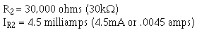
Solution:
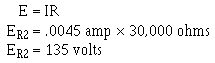
Figure 3-39. - Example problem parallel circuit.
Since the source voltage is equal to the voltage of a branch:

To simplify the math operation, the values can be expressed in powers of ten as follows:
If you are not familiar with the use of the powers of 10 or would like to brush up on it, Mathematics, Vol. 1, NAVEDTRA 10069-C, will be of great help to you.
What would the source voltage (ES) in figure 3-39 be if the current through R2 were 2 milliamps?
|
|


