Custom Search
|
|
 
|
||
|
Field Stripping the M16A1 Rifle The individual GM is authorized to disassemble the M16A1 to the extent called field stripping. Field stripping can be done without supervision and is adequate for normal maintenance. As the weapon is disassembled, the parts should be laid out on a table or other clean surface in the order of removal, from left to right. This makes assembly easier because the parts are assembled in the reverse order of disassembly. Nomenclature should be learned as the weapon is disassembled and assembled to enable the GM to better understand the function of the parts in the weapon. The steps infield stripping are as follows:
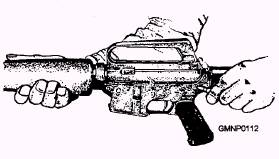
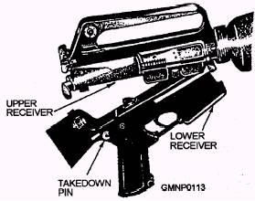
Figure 3-38.-Pressing the takedown pin to the right.
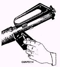
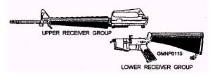
Figure 3-39.-Breaking the upper receiver away from the lower receiver. 1. Remove the sling and place the rifle on a table or flat surface, muzzle to the left. 2. Keeping the muzzle to the left, turn the weapon on its right side. Use a punch or the end of a cleaning rod (nose of cartridge used only as a last resort in the field) to press the takedown pin (fig. 3-38) until the upper receiver swings free of the lower receiver (fig. 3-39), NOTE The takedown pin does not come out of the receiver. 3. Again using a punch or the end of a cleaning rod, press the receiver pivot pin (fig. 3-40). Separate the upper and lower receiver groups (fig. 3-41) and place the lower receiver group on the table.
Figure 3-40.-Pressing out the receiver pivot pin.
Figure 3-41.-Upper and lower receiver groups.
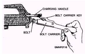
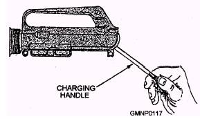
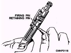
Figure 3-42.-Removing the bolt carrier from the receiver. NOTE The receiver pivot pin does not come out of the receiver. 4. Pick up the upper receiver group; keep the muzzle to the left. Grasp the charging handle, pressing in on the latch, and pull to the rear to withdraw the bolt carrier from the receiver. Grasp the bolt carrier and pull it from the receiver (fig. 3-42). When the bolt carrier is removed, the charging handle will fall free of its groove in the receiver (fig. 3-43). Place the receiver on the table. 5. To disassemble the bolt carrier group, press out the firing pin retaining pin by using a driftpin (fig. 3-44). Elevate the front of the bolt carrier and allow the firing
Figure 3-43.-Removing the charging handle.
Figure 3-44.-Pressing out the firing pin retaining pin.
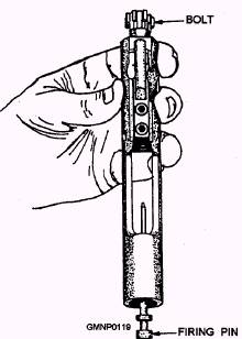
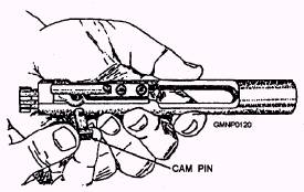
Figure 3-45.-Removing the firing pin. pin to drop from its well in the bolt (fig. 3-45). Rotate the bolt until the cam pin is clear of the bolt carrier key and remove the cam pin by rotating it 90 degrees (one-quarter turn) and lifting it out of the well in the bolt and bolt carrier (fig. 3-46). After the cam pin is
Figure 3-46.-Removing the cam pin.
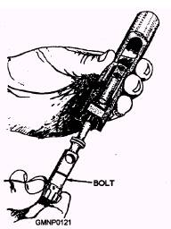
Figure 3-47.-Removing the bolt. removed, the bolt can be easily removed from its recess in the bolt carrier (fig. 3-47). |
||
|
||