Custom Search
|
|
 
|
||
|
Frames of Reference A frame of reference is a system of lines, angles, and planes, within which target position can be measured and lead angles computed. A position can be described only by relating it to a known reference point. A reference frame has a point, called the point of origin or reference point, from which all measurements are made. Two frames of reference are used by fire control systems. One is rigidly attached to the ship, while the other is considered rigidly attached to the surface of the Earth. The frame of reference of the ship has its point of origin built into the fire control system. All measurements are made from this point. This point is unstabilized, subject to the pitch and roll of the ship. The frame of reference of the Earth is a horizontal plane established by the stable element, independent of the pitch and roll of the ship.
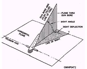
Figure 10-7.-Effect of drift. LINES.- Given the effects of exterior ballistics, two lines are required. One line, called the line of sight (LOS), is used to establish the present location of the target; the second line, called the line of fire (LOF), is used to establish the position of the gun bore with respect to the LOS. The LOS is the primary reference from which the offsets are made to establish the LOF. LEAD ANGLES.- Two lead angles are considered in the fire control problem- sight angle and sight deflection (fig. 10-8). Sight angle is the difference between the LOF and the LOS, measured on the plane perpendicular to the trunnion axis. Sight deflection is the angle that the plane through the gun bore is deflected left or right from the LOS. REFERENCE PLANES.- Reference planes are flat surfaces that may extend in all directions to infinity. Normally, these planes are pictured with boundaries equal to the range of the fire control problem, as shown in figure 10-9. The fire control system establishes target location as a point on a plane using the same three-coordinate system described earlier in this chapter. Once the position, speed, and direction of travel of the target are determined, its future position can be accurately predicted The steps in the solution of the fire control problem can be described as follows: l Determining present target location in relation to own ship l Predicting future target position in relation to own ship . Stabilizing the system
Figure 10-8.-Lead angles in a surface problem.
Figure 10-9.-Reference planes. ke Calculating the required correction to the gun or launcher train and elevation orders l Transmitting the data to the delivery device We have attempted to cover the basic elements involved in the fire control problem. Each element must be compensated for exactly, because once fired, a gun projectile cannot be redirected. The entire problem is, however, much more complex than the general description we have provided. The next section provides a more detailed description of the actual systems used in solving the gunfire control problem. |
 
|
|
|
||