Custom Search
|
|
 
|
||
|
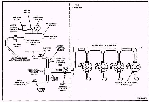
Sprinkler System Maintenance Sprinkler system maintenance is performed periodically under the Planned Maintenance System. We will describe some of the general procedures used during sprinkler testing. ALWAYS refer to the applicable maintenance instructions BEFORE performing ANY work. NOTE A test casting is treated as a controlled or accountable item. In other words, the commanding officer or a designated representative maintains custody of the test casting. Before any maintenance is started, two events must occur. First, permission must be obtained from proper authority to begin the work. Second, the test casting must be issued. After the work is finished, the test casting must be turned in. This issue/turn-in procedure assures command that the test casting is NOT accidentally left in the system. The first rule is to install the test casting. (The chief will INSIST on that!) Connect the fire hose and fitting to the test casting if the system is to be flushed. The next phase of the operation tests the automatic control system. Connect a tire (or bicycle) pump to the Schrader valve on the PRP valve. Stroke the pump slowly to pressurize the pneumatic system. That may take awhile as the entire pneumatic system is being filled. Do NOT exceed 16 osi on the air-pressure gauge during the pumping. Excess air pressure can damage the PRP valve/diaphragm. When system air pressure balances or equalizes near 16 osi, disconnect the pump and wait 5 minutes. If the pressure stabilizes within the 8-16 osi range, the system is satisfactorily airtight. A pressure drop below 8 osi indicates an air leak, which must be repaired. Use a leak-detector solution to find loose or cracked transmission line fittings, cracked HSD bellows, and so forth. If the system is "tight," CAREFULLY depress the stem of the Schrader valve. SLOWLY bleed the system to 8 osi. The PRP valve may, after repeated testings, be damaged if a higher pressure is used during the following step. The next phase of the operation tests the PRP valve, hydraulic control system, and main sprinkler control valve operation. Full y depress the Schrader valve stem. The air from the front side of the diaphragm will be vented quickly to the atmosphere. The 8 osi of air on the back side of the diaphragm causes it to move. The operating mechanism is released, the pilot valve trips, and the system activates. The system may be secured normally after it flushes for a few minutes. By the way, we hope you tied the end of the fire hose down. Unsecured, it will whip around under full fire main pressure. When testing is completed, ensure ALL the air is bled from the PRP valve. That is done by depressing the Schrader valve stem. The test casting is removed as the final step. Take your time during sprinkler system tests. Be sure you are performing each step correctly. The necessity to perform sprinkler system maintenance correctly cannot be overstressed. To emphasize this point, we will reprint a portion of an article that was published in the Ships Safety Bulletin. The Bulletin is a monthly publication prepared by the Naval Safety Center. The information contained in the Bulletin is intended for use by all hands. (The course number given at the end of the article may change, but otherwise the information remains valid.) MAGAZINE SPRINKLING SYSTEMS Inadvertent flooding of shipboard magazines are on the increase. Causes appear to be the unfamiliarity of personnel in operating and maintaining sprinkler system components, lack of formal training, improper supervision, and failure to follow prescribed PMS procedures. In one incident, a group of three magazines was inadvertently sprinkled because the petty officer in charge failed to ensure that proper step-by-step PMS procedures were followed. In completing PMS, the technician restored system lineup before air test pressure was fully bled off the pneumatically released pilot valve (PRP). Personnel error and haste were at the root of this mishap. NAVSEA OP-4, Vol. 2, Fifth Rev., Change 9, para. 3-22, requires that tests and maintenance of sprinkling systems be conducted in accordance with NAVSEA Technical Manual S9522-AA-HBK-010 and applicable PMS instructions. Formal training is available in the Sprinkler Systems School at the Fleet Training Centers in Norfolk and San Diego. Assistance can also be obtained from the Fleet Technical Support Center (FTSC) in your area. Actual GMLS Dry-Type Sprinkler Systems The dry-type, saltwater-operated, magazine sprinkler systems used by the Mk 13 and Mk 26 GMLSs and the Mk 41 VLS are similar. The remote control stations are located outside the launcher control rooms. The local control panels are located inside the magazine center areas. The HSDs and sprinkler heads are equally spaced around the missile cell/RSR areas. The Mk 41 VLS has its own uniquely designed damage control system known as deluge. The deluge system applies water directly to a missile when a restrained firing or canister overtemperature occurs. Restrained firing is defined as missile motor ignition and subsequent rupturing of the canister after closure, without missile motion. Overtemperature is defined as an internal canister temperature of 190F or above WITH a missile present. When either of the above conditions exists, a sensing device in the canister sends a deluge request to the deluge control circuits in the launch sequencer (LSEQ), which sends a DELUGE SYSTEM ON command to the motor control panel (MCP). The MCP determines which cell requires deluging and issues a DELUDE ON signal to cause deluging of that particular cell. A deluge control assembly (fig. 8-35), containing a solenoid control assembly, check valve, pilot valve, deluge control valve, and associated plumbing, is provided for each cell in the module. All eight assemblies (five for the strikedown module) are
Figure 8-35.-Deluge water supply and components. mounted on the inboard side of the modules above the upper walkway. A 28-gallon freshwater accumulator tank is filled with 15 gallons of freshwater and pressurized to 225 psi. An additional 50 gallons of freshwater is present in the launcher supply lines between the accumulator tank and the Hy-check deluge control valve. This water is used first, followed by the water from the accumulator tank. The water level in the accumulator tank is monitored by a sensing device. The sensing device sends a signal to both the status panel and central control station (CCS), causing an alarm indicating that the water level has dropped below 13 gallons. When the accumulator tank pressure drops below 190 psi, a signal is sent to both the status panel and CCS, causing another alarm. When the accumulator tank pressure drops below that of the ship's fire main, the Hy-check deluge control valve switches the system from freshwater to sea water to complete the deluge. The deluge flow rate is 40 gpm. The deluge is secured by an internal reset signal originated by the launch sequencer (LSEQ) after 100 seconds (10 seconds) or by manual operation of the DELUGE RESET switch on the status panel. A third method of securing the deluge is by operation of the deluge two-way manual control valve, which secures the saltwater supply. When a deluge condition is initiated in a particular cell, any cell in that module which has been deluged before that time will be deluged again. This deluge operation will continue until the deluged canisters have been replaced. Also, any empty canisters in the module concerned are deluged.
|
 
|
|
|
||