Custom Search
|
|
 
|
||
|
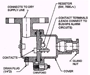
Sprinkler Alarm System Two water-activated switches serve as the alarm portion of the system. Both units are located on the dry or downstream side of the main sprinkler control valve. (See fig. 8-28.) The leakage alarm switch (fig. 8-34) is the early warning unit. The seat of the main control valve can become deteriorated through age. A piece of marine growth (like a seashell) can get caught on the seat when the valve Closes. In either case, saltwater will leak by and enter the switch body. Because water is a good conductor of electricity, it activates the switch element.
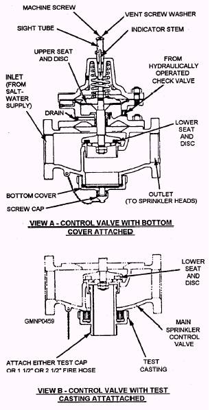
Figure 8-33.-Main sprinkler control valve.
Figure 8-34.-Leakage alarm switch. An alarm is energized in DC central on the FH (water) circuit. The operation alarm or flow alarm switch is installed farther downstream from the main valve. (See fig. 8-28.) When the system is activated, fire main pressure actuates this switch to set off other FH alarms in DC central. Sprinkler System Operation Refer to figure 8-28 as we describe a remote START and a remote STOP sprinkler operation. At the remote control station, the lead-wire seal is broken and the locking key removed. The handle and lever of the valve are squeezed together and turned to the START position. (When the locking pin engages its recess hole, you can let goof the handle.) Fire main control pressure flows through one of the inline check valves on the local board. (Trace the water flow on the figure.) The control pressure flows to the top of the main sprinkler control valve, which lifts to start sprinkling operations. Control pressure also flows to the bottom chamber of the hydraulically operated check valve. A small amount of water flows out drain line #1. The other two drain lines will be dry at this time. (If you forgot to put the test casting in, your missiles are getting wet !) When the system must be secured, the remote control valve handle and lever are squeezed and turned to CLOSED. Fire main control pressure is rerouted through the stop line to another inline check valve. Control pressure enters the upper chamber of the hydraulically operated check valve, causing it to lift. The control pressure in the upper chamber of the main sprinkler valve is then vented. It flows through the hydraulically y operated check valve and out drain line #3. As the pressure decreases, the main sprinkler valve closes. After the main sprinkler control valve has seated, the remote control valve may be returned to OPEN. Fire main control pressure is then isolated from the hydraulic control system. The hydraulically operated check valve will be closed by its spring as water pressure decreases. Any remaining pressure in the lines is bled through the #1 and #2 orifice drains. The other operational possibilities will not be described in detail. The major steps for two such sequences are listed below. Refer to figure 8-28 as you run the cycles. Remote station OPEN and local station CLOSED: 1 Remote-Turned to OPEN 2. Local-Turned to CLOSED 3. Remote-Turned to NEUTRAL 4. Local-Turned to NEUTRAL Automatic (PRP valve) OPEN and remote station CLOSED: 1. PRP valve-Trips 2. Remote-Turned to CLOSED 3. PRP valve-Reset manually 4. Remote--Tumed to NEUTRAL |
 
|
|
|
||