Custom Search
|
|
 
|
||
|
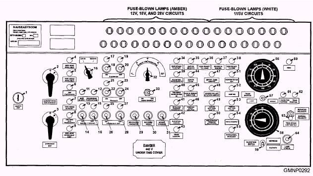
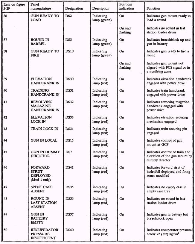
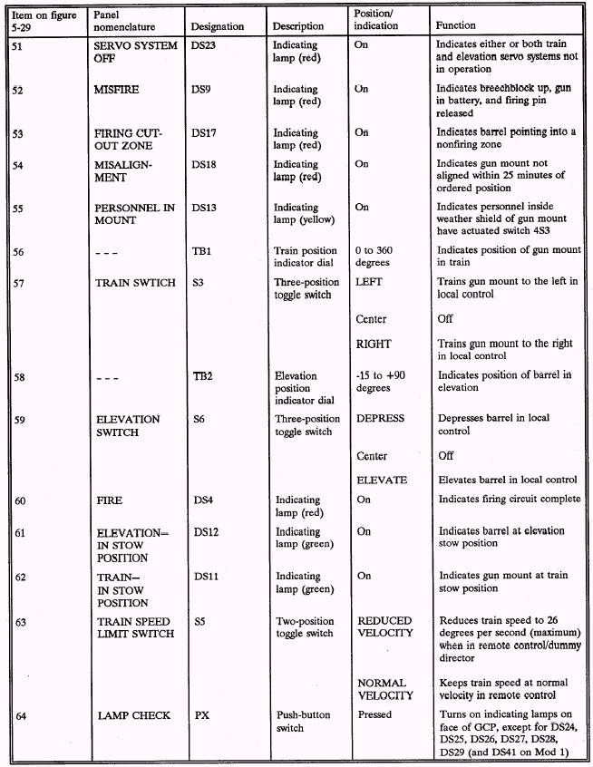
MK 75 GUN MOUNT CONTROL SYSTEM LEARNING OBJECTIVE: Recall general information concerning the Mk 75 gun mount control system. The Mk 75 gun mount control system consists of the equipment used to distribute power to the gun-loading and gun-laying systems. It includes equipment required to activate, control, monitor, and test gun mount operations, and equipment required to prevent excessive gun barrel temperatures during firing operations. The gun mount control system also includes equipment required to prevent ice from forming on the gun port shield and the roller path assembly during cold weather operations. This section will cover only a general description of the Mk 75 gun mount control system. For a more detailed and in-depth description, refer to the Technical Manual for 76-mm 62-Caliber Gun Mount Mark 75 Mods 0 and 1, SW314-AO-MMM-A10/GM MK75 0-1 series. GUN CONTROL PANEL (GCP) The gun control panel (GCP) (fig. 5-29 and table 5-3), located in the ammunition handling room, provides the intermediate link between the fire control system (FCS) and the gun mount. The GCP includes solid-state plug-in modules that contain the electronic control circuits for the gun mount systems. The GCP also includes transformers, circuit breakers, indicating lamps, control switches, train and elevation position dials, and the train and elevation toggle switches. Transformers convert ships power to the voltages needed for gun mount electrical and electronic systems and components. Circuit breakers permit the distribution of this power to the hydraulic power unit, the servo system, and the other gun mount electrical systems. Indicating lamps provide visual indications of the gun status and permit the GCP operator to monitor" gun mount systems. Control switches permit local control of the gun systems for maintenance and test purposes. Control switches also enable the GCP operator to load ammunition to the last station loader drum. The train and elevation position dials permit these positions to be monitored from the GCP. Train and elevation toggle
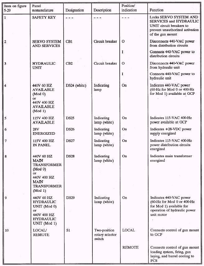
Figure 5-29.-Gun control panel. Table 5-3.-GCP: Controls and Indicators 5-28
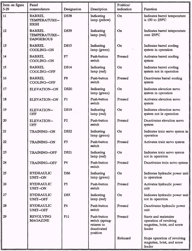
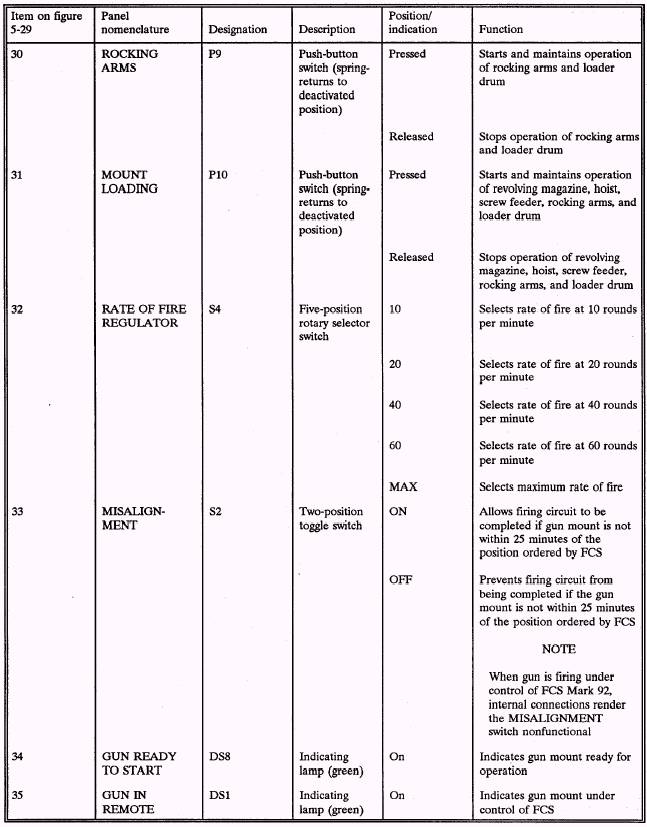
Table 5-3.-GCP: Controls and Indicators-Continued
Table 5-3.-GCP: Controls and Indicators-Continued
Table 5-3.-GCP: Controls and Indicators-Continued
Table 5-3.-GCP: Controls and Indicators-Continued
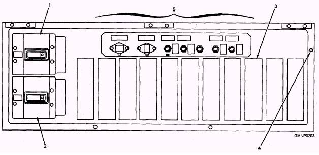
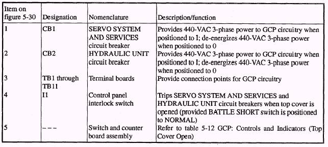
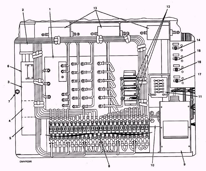
Figure 5-30.-Inside top cover of GCP. switches permit local control of the train and elevation systems (at low speed only). When the gun mount is operated in remote control, the GCP receives control inputs directly from FCS. When the gun mount is operated in the remote mode, the GCP is normally used to monitor system functions and gun status. The equipment of the GCP is organized into compartments. Each compartment permits ready accessibility for maintenance and testing. An interlock switch under each compartment cover opens the GCP circuit breakers when the cover is removed. The following locations provide access to equipment and test points at the GCP 1. Inside top cover 2. Inside top compartment 3. Inside bottom compartment 4. Right side 5. Left side Inside Top Cover The top cover of the GCP is hinged in the back and secured in the front with cap screws. With the top cover open (fig. 5-30), access is provided to the components listed in table 5-4. Table 54.-Inside Top Cover of GCP
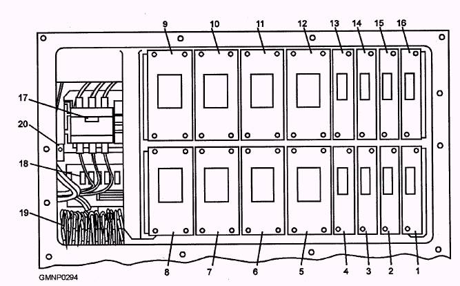
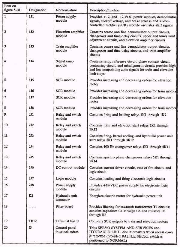
Figure 5-31.-Inside top compartment of GCP. Inside Top Compartment The top compartment of the GCP (fig. 5-31) is also protected by a cover plate secured with cap screws. With the cover removed, access is provided to the plug-in modules and components listed in table 5-5. Table 5-5.-Inside Top Compartment of GCP
Figure 5-32.-Inside bottom compartment of GCP. |
 |
|
|
||