Custom Search
|
|
 
|
||
|
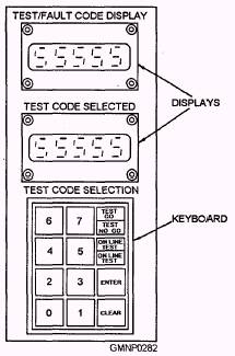
Troubleshooting Logic Circuits The Mk 45 Mod 1 gun system is equipped with a microprocessor that monitors the sequence of operation of the gun through equipment position switch inputs. Notice the last output destination on the 1 and 2 legs of the inverter buffer circuit shown in figure 5-18. p INPUT indicates that switch output is supplied to the microprocessor. On the EP-2 panel there is a Test/Fault Code Keyboard and Display (fig. 5-19) that is used to interface with the microprocessor. To test the output of a switch or summary circuit, the operator needs only to type in the test number for that circuit or switch. The result of the testis displayed as a 0 or a 1 in the Test/Fault Code Display above the keyboard. A zero (0) indicates a LOW output and a one (1) indicates a HIGH output. In this case, the test number for SIB4 is 1476 for leg 1 and 1466 for leg 2 (fig. 5-19). The test code number is
Figure 5-19.-Test/Fault code keyboard and displays. displayed in brackets along with the circuit or switch input/output identification (note the same number [1476] in the SIB4-1 input to gate 1 in fig. 5-17). Logic circuit failures are isolated much the same as they are in the older types of control circuits. Refer to figure 5-17 as we walk through a typical troubleshooting routine. You have verified equipment position and determined that the equipment stopped at the CLOSE BREECH step in the loading sequence. The first problem is to isolate the fault to one side of the circuit. This is done by entering the test code for QCB1-1 [1633]. A LOW would indicate the problem is in the right side of the circuit, in gate 6-the solenoid driver or the solenoid. Let us assume we read a HIGH here, the problem is in the left side of the circuit. Since there are no test codes for gates 3,4, and 5, we skip over to the switch inputs for gates 1 and 2. If all the inputs to gates 1 and 2 are LOW, the problem is on board 62. A HIGH at any of these test points would lead you back through the inverter buffer circuit for that input. In this case we will assume a HIGH input is detected at SIB4-1. Refer to figure 5-18 as we examine the inverter buffer for SIB4. Since we have read a HIGH at leg 1, test code [1476], we can assume the inverter buffer is functioning if we read a LOW on leg 2, test code [1466]. These tests lead us back to the proximity switch. After verifying that the switch is in proximity, we test the switch by checking switch input at point 8-71. This test is accomplished using a circuit card extender. The circuit card extender allows you to take input and output readings on a particular circuit card while the system is energized. The circuit card extender provides an extended circuit card jack with test points for each pin connection. A LOW reading at pin 8-71 would indicate a bad proximity switch. WARNING The system should always be de-energized when removing electronic components to avoid shock hazard and damage to the equipment. If a fault is isolated to a circuit card, the system provides a test slot to verify your diagnosis. Simply insert the suspected card in the test slot and enter the appropriate test code for that type of card. Fault Codes In some cases, a malfunction in the system will be detected and presented as a fault code on the Test/Fault Code Display. The fault codes are defined in volume 1 of the system OP along with a systematic procedure for isolating the defective component. |
||
|
||