| Tweet |

Custom Search
|
|
 
|
||
|
RELATIONSHIP OF FORCE, PRESSURE,
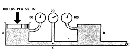
AND HEAD In dealing with fluids, forces are usually considered in relation to the areas over which they are applied. As previously discussed, a force acting over a unit area is a pressure, and pressure can alternately be stated in pounds per square inch or in terms of head, which is the vertical height of the column of fluid whose weight would produce that pressure.In most of the applications of fluid power in the Navy, applied forces greatly outweigh all other forces, and the fluid is entirely confined. Under these circumstances it is customary to think of the forces involved in terms of pressures. Since the term head is encountered frequently in the study of fluid power, it is necessary to understand what it means and how it is related to pressure and force.All five of the factors that control the actions of fluids can, of course, be expressed either as force, or in terms of equivalent pressures or head. In each situation, the different factors are referred to in the same terms, since they can be added and subtracted to study their relationship to each other.At this point you need to review some terms in general use. Gravity head, when it is important enough to be considered, is sometimes referred to as head. The effect of atmospheric pressure is referred to as atmospheric pressure. (Atmospheric pressure is frequently and improperly referred to as suction.) Inertia effect, because it is always directly related to velocity, is usually called velocity head; and friction, because it represents a loss of pressure or head, is usually referred to as friction head.STATIC AND DYNAMIC FACTORS Gravity, applied forces, and atmospheric pressure are static factors that apply equally to fluids at rest or in motion, while inertia and friction are dynamic factors that apply only to fluids in motion. The mathematical sum of gravity, applied force, and atmospheric pressure is the static pressure obtained at any one point in a fluid at any given time. Static pressure exists in addition to any dynamic factors that may also be present at the same time.Remember, Pascals law states that a pressure set up in a fluid acts equally in all directions and at right angles to the containing surfaces. This covers the situation only for fluids at rest or practically at rest. It is true only for the factors making up static head. Obviously, when velocity becomes a factor it must have a direction, and as previously explained, the force related to the velocity must also have a direction, so that Pascals law alone does not apply to the dynamic factors of fluid power.The dynamic factors of inertia and friction are related to the static factors. Velocity head and friction head are obtained at the expense of static head. However, a portion of the velocity head can always be reconverted to static head. Force, which can be produced by pressure or head when dealing with fluids, is necessary to start a body moving if it is at rest, and is present in some form when the motion of the body is arrested; therefore, whenever a fluid is given velocity, some part of its original static head is used to impart this velocity, which then exists as velocity head.BERNOULLIS PRINCIPLE Consider the system illustrated in figure 2-18. Chamber A is under pressure and is connected by a tube to chamber B, which is also under pressure. The pressure in chamber A is static pressure of 100 psi. The pressure at some point (X) along the connecting tube consists of a velocity pressure of
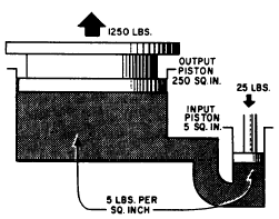
Figure 2-18.Relation of static and dynamic factors Bernoullis principle. 10 psi exerted in a direction parallel to the line of flow, plus the unused static pressure of 90 psi, which still obeys Pascals law and operates equally in all directions. As the fluid enters chamber B it is slowed down, and its velocity is changed back to pressure. The force required to absorb its inertia equals the force required to start the fluid moving originally, so that the static pressure inchamber B is equal to that in chamber A. This situation (fig. 2-18) disregards friction; therefore, it would not be encountered in actual practice. Force or head is also required to overcome friction but, unlike inertia effect, this force cannot be recovered again, although the energy represented still exists somewhere as heat. Therefore, in an actual system the pressure in chamber B would be less than in chamber A by the amount of pressure used in overcoming friction along the way. At all points in a system the static pressure is always the original static pressure, less any velocity head at the point in question and less the friction head consumed in reaching that point. Since both the velocity head and the friction head represent energy that came from the original static head, and since energy cannot be destroyed, the sum of the static head, the velocity head, and the friction head at any point in the system must add up to the original static head. This is known as Bernoulli's principle, which states: For the horizontal flow of fluid through a tube, the sum of the pressure and the kinetic energy per unit volume of the fluid is constant. This principle governs the relations of the static and dynamic factors concerning fluids, while Pascals law states the manner in which the static factors behave when taken by themselves. MINIMIZING FRICTION Fluid power equipment is designed to reduce friction to the lowest possible level. Volume and velocity of flow are made the subject of careful study. The proper fluid for the system is chosen. Clean, smooth pipe of the best dimensions for the particular conditions is used, and it is installed along as direct a route as possible. Sharp bends and sudden changes in cross-sectional areas are avoided. Valves, gauges, and other components are designed to interrupt flow as little as possible. Careful thought is given to the size and shape of the openings. The systems are designed so they can be kept clean inside and variations from normal operation can easily be detected and remedied. OPERATION OF HYDRAULIC COMPONENTS To transmit and control power through pressurized fluids, an arrangement of inter-connected components is required. Such an arrangement is commonly referred to as a system. The number and arrangement of the components vary from system to system, depending on the particular application. In many applications, one main system supplies power to several subsystems, which are sometimes referred to as circuits. The complete system may be a small compact unit; more often, however, the components are located at widely separated points for convenient control and operation of the system. The basic components of a fluid power system are essentially the same, regardless of whether the system uses a hydraulic or a pneumatic medium. There are five basic components used in a system. These basic components are as follows: 1. Reservoir or receiver 2. Pump or compressor 3. Lines (pipe, tubing, or flexible hose) 4. Directional control valve 5. Actuating device Several applications of fluid power require only a simple system; that is, a system which uses only a few components in addition to the five basic components. A few of these applications are presented in the following paragraphs. We will explain the operation of these systems briefly at this time so you will know the purpose of each component and can better understand how hydraulics is used in the operation of these systems. More complex fluid power systems are described in chapter 12. HYDRAULIC JACK The hydraulic jack is perhaps one of the simplest forms of a fluid power system. By moving the handle of a small device, an individual can lift a load weighing several tons. A small initial force exerted on the handle is transmitted by a fluid to a much larger area. To understand this better, study figure 2-19. The small input piston has an area of 5 square inches and is directly connected to a large cylinder with an output piston having an area of 250 square inches. The top of this piston forms a lift platform. If a force of 25 pounds is applied to the input piston, it produces a pressure of 5 psi in the fluid, that is, of course, if a sufficient amount of resistant force is acting against the top of the output piston. Disregarding friction loss, this pressure acting on the 250 square inch area of the output piston will support a resistance force of 1,250 pounds. In other words, this pressure could overcome a force of slightly under 1,250 pounds. An input force of 25 pounds has been transformed into a working force of more than half a ton; however, for this to be true, the distance traveled by the input piston must be 50 times greater than the distance traveled by the output piston. Thus, for every inch that the input piston moves, the output piston will move only one-fiftieth of an i n c h. This would be ideal if the output piston needed to move only a short distance. However, in most instances, the output piston would have to be capable of moving a greater distance to serve a practical application. The device shown in figure 2-19 is not capable of moving the output piston farther than that shown; therefore, some other means must be used to raise the output piston to a greater height.
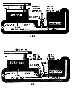
Figure 2-19.Hydraulic jack. The output piston can be raised higher and maintained at this height if additional components are installed as shown in figure 2-20. In this illustration the jack is designed so that it can be raised, lowered, or held at a constant height. These results are attained by introducing a number of valves and also a reserve supply of fluid to be used in the system. Notice that this system contains the five basic componentsthe reservoir; cylinder 1, which serves as a pump; valve 3, which serves as a directional control valve; cylinder 2, which serves as the actuating device; and lines to transmit the fluid to and from the different components. In addition, this system contains two valves, 1 and 2, whose functions are explained in the following discussion. As the input piston is raised (fig. 2-20, view A), valve 1 is closed by the back pressure from the weight of the output piston. At the same time, valve 2 is opened by the head of the fluid in the reservoir. This forces fluid into cylinder 1. When the input piston is lowered (fig. 2-20, view B), a pressure is developed in cylinder 1. When this pressure exceeds the head in the reservoir, it closes valve 2. When it exceeds the back pressure from the output piston, it opens valve 1, forcing fluid into the pipeline. The pressure from cylinder 1 is
Figure 2-20.Hydraulic jack; (A) up stroke; (B) downstroke. thus transmitted into cylinder 2, where it acts to raise the output piston with its attached lift platform. When the input piston is again raised, the pressure in cylinder 1 drops below that in cylinder 2, causing valve 1 to close. This prevents the return of fluid and holds the output piston with its attached lift platform at its new level. During this stroke, valve 2 opens again allowing a new supply of fluid into cylinder 1 for the next power (downward) stroke of the input piston. Thus, by repeated strokes of the input piston, the lift platform can be progressively raised. To lower the lift platform, valve 3 is opened, and the fluid from cylinder 2 is returned to the reservoir. |
||
|
||