| Tweet |

Custom Search
|
|
 
|
||
|
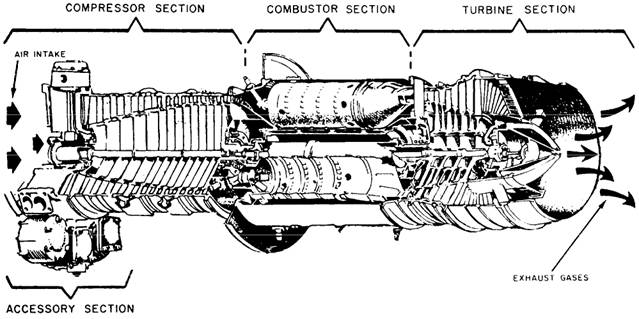
CLASSIFICATION BY POWER USAGE There are basically three types of gas turbines in use. They are the single shaft, split shaft, and twin spool. Of these, the single shaft and split shaft are the most common in naval vessels. We mention the twin-spool type because the U.S. Coast Guard Hamilton class cutters use the twinspool gas turbine. In current U.S. Navy service, the single-shaft engine is used primarily for driving ship's service generators. The split-shaft engine is used for main propulsion. Figure 6-13 is a block diagram of a single-shaft gas turbine. The power output shaft is connected directly to the same turbine rotor that drives the compressor. In most cases, there is a speed decreaser or reduction gear between the rotor and the power output shaft. However, there is still a mechanical connection throughout the entire engine. The arrangement shown is typical for the gas turbine generator sets aboard DD-963 and CG-47 class ships. In the split-shaft gas turbine fig 6-14 , there is no mechanical connection between the gasgenerator turbine and the power turbine. The power turbine is the component that does the usable work. The gas-generator turbine provides the power to drive the compressor and accessories. With this type of engine, the output speed can be varied by varying the gas generator speed. Also, under certain conditions, the gas generator can run at a reduced rpm and still provide maximum power turbine rpm. This greatly improves fuel economy and also extends the life of the gasgenerator turbine. The arrangement shown in (fig 6-15) is typical for propulsion gas turbines aboard the DD-963, FFG-7, CG-47, and PHM-1 class ships. ENGINE CONSTRUCTION Recall that a gas turbine engine is composed of four major sections ~: (1) compressor, (2) combustor, (3) turbine, and (4) accessory. We will briefly discuss the construction and function of each of these sections. We will use the LM2500 gas turbine as an example. The LM2500 is a splitshaft gas turbine.
Figure 6-15.-Typical gas turbine.
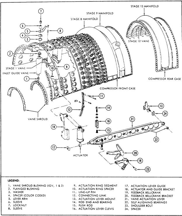
Figure 6-16.-Compressor case, LM2500 engine. Compressor The rotor and stators are enclosed in the compressor case (fig 6-16) . Modern engines use a case that is horizontally divided into upper and lower halves. The halves are normally bolted together with either dowel pins or fitted bolts. These parts ensure proper alignment to each other and in relation to other engine assemblies that bolt to either end of the compressor case. On some older engines, the case is a one-piece cylinder open on both ends. The one-piece compressor case is simpler to manufacture; however, any repair or detailed inspection of the compressor rotor is impossible. The engine must be removed and taken to a shop where it can be disassembled for repair or inspection of the rotor or stators. On many split-case engines, either the upper or lower case can be removed for maintenance and inspection with the engine in place. The compressor case is usually made of aluminum or steel. The material used will depend on the engine manufacturer and the accessories attached to the case. The compressor case may have external connections made as part of the case. These connections are normally used to bleed air during starting and acceleration or at low-speed operation. Preceding the stators and the first stage of the compressor rotor is a row of IGVs. The function of the IGVs varies somewhat, depending on the size of the engine and air-inlet construction. On smaller engines, the air inlet is not totally in line with the first stage of the rotor. The IGVs straighten the airflow and direct it to the first-stage rotor. On large engines, the IGVs can be moved to direct the airflow at the proper angle to reduce drag on the first-stage rotor. Small and medium engines have stationary stators. On large engines, the pitch of the vanes on several stators can be changed. For example, in the LM2500 engine fig. 6-16 the first six stators of the 16-stage rotor are variable, Rotor blades fig. 6-17 are usually made of stainless or iron-based, super-strength alloys. Methods of attaching the blades in the rotor disk rims vary in different designs, but they are commonly fitted into disks by either bulb (fig 6-17 view A) or fir-tree (fig 6-17 view B) type roots. The blades are then locked with grub screws, peening, lockwires, pins, or keys. The stator vanes project radially toward the rotor axis and fit closely on either side of each stage of the rotor. The stators have two functions. They receive air from the air inlet duct or from each preceding stage of the rotor and then deliver the air to the next stage or to combustors at a workable velocity and pressure. They also control the direction of air to each rotor stage to obtain the maximum compressor-blade efficiency. The stator vanes are usually made of steel with corrosion- and erosion-resistant qualities. Frequently, the vanes are shrouded by a band of suitable material to simplify the fastening problem. The vanes are welded into the shrouds, and the outer shrouds are secured to the inner wall of the compressor case by retaining screws. Combustion Chambers There are three types of combustion chambers: (1) can type, (2) annular type, and (3) can-annular type. The can-type chamber is used primarily on
Figure 6-17.-Rotor blades.
engines that have a centrifugal compressor. The annular and can-annular types are used on axialflow compressors. The combustion chambers have presented one of the biggest problems in gas turbines. The extreme stresses and temperatures encountered are not experienced in other types of internalcombustion engines. The liners are subjected to temperatures as high as 4000F in a matter of seconds. The combustion chamber must operate over a wide range of conditions. It must withstand high rates of burning, have a minimum pressure drop, be light in weight, and have minimum bulk. The inner and outer liners or shrouds are perforated with many holes and slots throughout their length. Air is admitted through these holes to protect the liner and to cool the gases at the chamber outlet. The through-flow passages are used in practically all modern engine combustion chambers. In the through-flow path, the gases pass through the combustion section without a change in direction. The annular combustor liner (fig 6-18) is usually found on axial-flow engines. It is probably one of the most popular combustion systems in use. The construction consists of a housing and liner. On large engines, the liner consists of an undivided circular shroud extending all the way around the outside of the turbine shaft housing. A large one-piece combustor case covers the liner and is attached at the turbine section and diffuser section. The dome of the liner has small slots and holes to admit primary air and to impart a swirling motion for better atomization of fuel. There are also holes in the dome for the fuel nozzles to extend through into the combustion area. The inner and outer liners form the combustion space. The outer liner keeps flame from contacting the combustor case, and the inner liner prevents flame from contacting the turbine shaft housing. Large holes and slots are located along the liners to (1) admit some cooling air into the
Figure 6-18.-Combustor liner. combustion space towards the rear of the space to help cool the hot gases to a safe level, (2) center the flame, and (3) admit air for combustion. The gases are cooled enough to prevent warpage of the liners. The space between the liners and the case and shaft housing forms the path for secondary air. The secondary air provides film cooling of the liners and the combustor case and shaft housing. At the end of the combustion space and just before the first-stage turbine nozzle, the secondary air is mixed with the combustion gases to cool them enough to prevent warping and melting of the turbine section. The annular-type combustion chamber is a very efficient system that minimizes bulk and can be used most effectively in limited space. There are some disadvantages, however. On some engines, the liners are one-piece and cannot be removed without engine disassembly. Turbines In theory, design, and operating characteristics, the turbines used in gas turbine engines are quite similar to the turbines used in a steam plant. The gas turbine differs from the steam turbine chiefly in (1) the type of blading material used, (2) the means provided for cooling the turbine shaft bearings, and (3) the lower ratio of blade length to wheel diameter. The terms gas generator turbine and power turbine are used to differentiate between the turbines. The gas-generator turbine powers the gas generator and accessories. The power turbine powers the ship's propeller through the reduction gear and shafting. The turbine that drives the gas generator is located directly behind the combustion chamber outlet. This turbine consists of two basic elements: the stator or nozzle and the rotor. Part of a stator
Figure 6-19.-Stator element of turbine assembly. element is shown in figure 6-19. A rotor element is shown in figure 6-20. The rotor element of the turbine consists of a shaft and bladed wheel(s). The wheel(s) are attached to the main power transmitting shaft of the gas turbine engine. The jets of combustion gas leaving the vanes of the stator element act upon the turbine blades and cause the turbine wheel to rotate in a speed range of 3,600 to 42,000 rpm, depending upon the type of engine. The high rotational speed imposes severe centrifugal loads on the turbine wheel. At the same time, the high temperature (1050 to 2300 F) results in a lowering of the strength of the material. Consequently, the engine speed and temperature must be controlled to keep turbine operation within safe limits. The operating life of the turbine blading usually determines the life of the gas turbine engine. The turbine wheel is a dynamically balanced unit consisting of blades attached to a rotating disk. The disk, in turn, is attached to the rotor shaft of the engine. The high-velocity exhaust gases leaving the turbine nozzle vanes act on the blades of the turbine wheel. This causes the assembly to rotate at a high rate of speed. This turbine rotation, in turn, causes the compressor to rotate.
Figure 6-20.-Rotor element of turbine assembly.
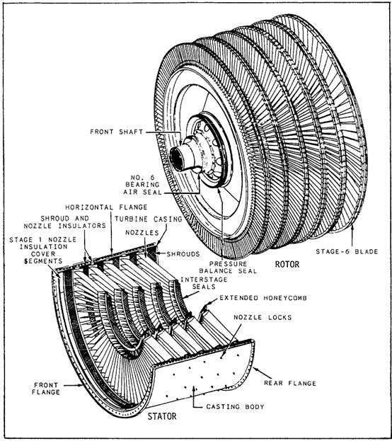
Figure 6-21.-Power turbine. The power turbine fig. 6-21 is a multistage unit located behind the gas-generator turbine. There is no mechanical connection between the two turbines. The power turbine is connected to a reduction gear through a clutch mechanism. A controllable reversible-pitch (CRP) propeller is used to change direction of the vessel. Accessories Because the turbine and the compressor are on the same rotating shaft, a popular misconception is that the gas turbine engine has only one moving part. This is not so. A gas turbine engine requires a starting device, some kind of control mechanism, and power takeoffs for lube oil and fuel pumps. The accessory drive section (fig 6-15) of the gas turbine engine takes care of these various accessory functions. The primary purpose of the accessory drive section is to provide space for the mounting of the accessories required for the operation and control of the engine. The accessory drive section also serves as an oil reservoir and/or sump and houses the accessory drive gears and reduction gears. The gear train is driven by the engine rotor through an accessory drive shaft gear coupling. The reduction gearing within the case provides suitable drive speeds for each engine accessory or component. The accessory drives are supported by ball bearings assembled in the mounting bores of the accessory case. Accessories usually provided in the accessory drive section include the fuel control (with its governing device), the high-pressure fuel-oil pump or pumps, the oil sump, the oil pressure and scavenging pump or pumps, the auxiliary fuel pump, and a starter. Additional accessories, which may be included in the accessory drive section or which may be provided elsewhere, include a starting fuel pump, a hydraulic oil pump, a generator, and a tachometer. Most of these accessories are essential for the operation and control of any gas turbine engine. However, the particular combination and arrangement and location of engine-driven accessories depend on the use for which the gas turbine engine is designed. The three common locations for the accessory section are on the side of the air inlet housing, under the compressor front frame, or under the compressor rear frame. |
||
|
||