| Tweet |

Custom Search
|
|
 
|
||
|
GAS TURBINE ENGINE TYPES AND CONSTRUCTION There are two primary means of classifying gas turbine engines: (1) by the type of compressor used and (2) by how the power is used. The centrifugal compressor draws in air at the center or eye of the impeller and accelerates it around and outward. It consists of an impeller, a diffuser, and a compressor manifold. The diffuser is bolted to the manifold, and often the entire assembly is referred to as the diffuser. For ease of understanding, we will treat each unit separately. The impeller may be either single entry or dual entry (fig 6-10) The principal differences between the single entry and dual entry are the size of the impeller and the ducting arrangement. The singleentry impeller (fig. 6-10 view A) permits ducting directly to the inducer vanes, as opposed to the more complicated ducting needed to reach the rear side of the dual-entry type. Although slightly more efficient in receiving air, single-entry impellers must be of greater diameter to provide sufficient air. Dual-entry impellers fig 6-10 view B) are smaller in diameter and rotate at higher speeds to ensure sufficient airflow. Most gas turbines of modern design use the dual-entry compressor to reduce engine diameter. A plenum (an enclosure in which air is at a pressure greater than that outside the enclosure) chamber is also required for dual-entry compressors, since the air must enter the engine at almost right angles to the engine axis. The air must surround the compressor at positive pressure to give positive flow. The compressor draws in air at the hub of the impeller and accelerates it radially outward by centrifugal force through the impeller. It leaves the impeller at high speed and low pressure and flows through the diffuser, (fig 6-10 view A). The diffuser converts the high-speed, low-pressure air to low-speed, high-pressure air. The compressor manifold diverts the low-speed, high-pressure air from the diffuser into the combustion chambers. In this design, the manifold has one outlet port for each combustion chamber. The outlet ports are bolted to an outlet elbow on the manifold. The outlet ports ensure that the same amount of air is delivered to each combustion chamber. The outlet elbows (known by a variety of names) change the airflow from radial to axial flow. The diffusion process is completed after the turn. Each elbow contains from two to four turning vanes that perform the turning process and reduce air pressure losses by providing a smooth turning surface. AXIAL-FLOW COMPRESSOR In the axial-flow engine, the air is compressed while continuing its original direction of flow
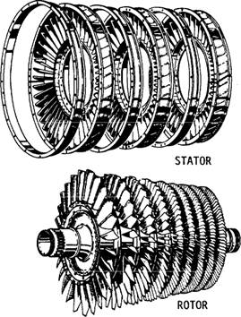
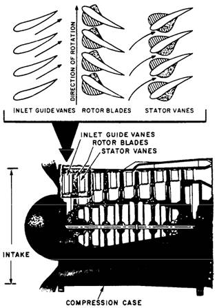
Figure 6-11.-Stator and rotor components of an axial-flow compressor. parallel to the axis of the compressor rotor. The compressor is located at the very front of the engine. The purpose of the axial compressor is to take in ambient air, increase the speed and pressure, and discharge the air through the diffuser into the combustion chamber. The two main elements of an axial-flow compressor are the rotor and stator (fig 6-11). The rotor is the rotating element of the compressor. The stator is the fixed element of the compressor. The rotor and stator are enclosed in the compressor case. The rotor has fixed blades that force the air rearward much like an aircraft propeller. In front of the first rotor stage are the inlet guide vanes (IGVs). These vanes direct the intake air toward the first set of rotor blades. Directly behind each rotor stage is a stator. The stat or directs the air rearward to the next rotor stage (fig 6-12). Each consecutive pair of rotor and stator blades constitutes a pressure stage.
Figure 6-12.-Operating principle of an axial-flow compressor.
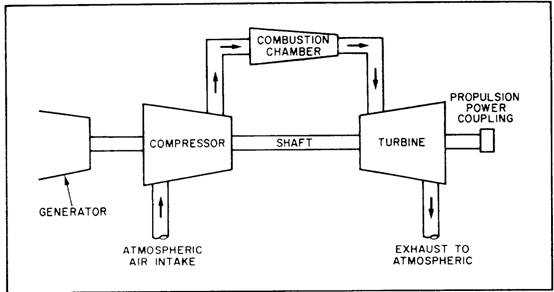
Figure 6-13.-Single-shaft gas turbine.
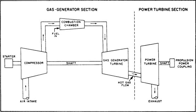
Figure 6-14.-Split-shaft gas turbine. The action of the rotor increases air compression at each stage and accelerates the air rearward. By virtue of this increased velocity, energy is transferred from the compressor to the air in the form of velocity energy. The number of stages required is determined by the amount of air and total pressure rise required. The greater the number of stages, the higher the compression ratio. Most present-day engines have 8 to 16 stages. |
||
|
||