| Tweet |

Custom Search
|
|
 
|
||
|
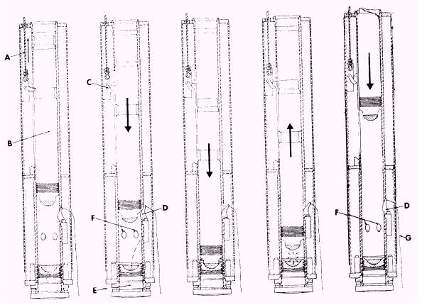
Diesel Hammer Operation The most common diesel hammer used in the NCF is the DE-10 McKiernan-Terry pile hammer shown in figure 12-61. The hammer is lifted and started by a single crane load line connected to a trip mechanism (A). The hammer is started by lifting the ram piston (B) with the load line until the trip mechanism (C) automatically releases the ram piston. The ram piston falls and actuates the cam of the fuel pump (D) that delivers a measured amount of diesel fuel that falls into a cup formed in the top of the anvil (E). Continuing its downfall, the ram piston blocks the exhaust ports (F) and begins compression of air trapped between the ram piston and the anvil. The compression of the trapped air creates a preloading force upon the anvil, the drive cap, and the pile. The gravity propelled ram piston strikes the anvil, delivering its impact energy to the pile. The rounded end of the ram piston mates perfectly with the cup in the anvil and displaces the fuel at the
Figure 12-61.-Operating principles of the McKiernan-Terry diesel pile hammer. precise moment of impact for perfect timing. The fuel is atomized and splattered into the annular (ring-shaped) zone between the ram and the anvil and is ignited by the heat of compression. The resulting explosive force drives the ram piston upward and the pile downward and adds a push to the pile to extend the time of the total effort to drive the pile. On the upstroke, the ram piston opens the exhaust ports (F) to permit scavenging the exhaust gases. The ram piston continues freely upward until arrested by gravity. The length of the stroke varies with the resistance of the pile. The greater the resistance, the longer the stroke. Having reached the top of its stroke, the ram piston falls again, repeating the cycle. The hammer is stopped by pulling a rope (G) that disengages the fuel pump cam (D). TRIP MECHANISM.- The trip mechanism (fig. 12-62) is an off-center linkage mechanism located at the rear of the hammer, designed to lift and drop the ram for starting. Additionally, the trip mechanism lifts and lowers the hammer in the leads. The trip mechanism is connected to a single line from the crane. Lowering the trip mechanism to the bottom of its stroke engages the lifting lever that lifts the ram. When the crane lifts the trip mechanism and ram piston past the upper stops, the finger of the trip lever is rotated clockwise around the trip lever pin, thus freeing the ram piston. The trip mechanism is held in the upper position while the hammer is in operation. The safety link in the trip mechanism is designed to break or bend should the operator lower the trip mechanism to low and engage the lifting lever while the hammer is in operation. The safety link prevents damaging the trip mechanism or ram. If the safety link is broken while the hammer is in operation, the hammer will continue to operate; however, once the hammer is shut down, the safety link must be replaced before the hammer can be restarted.
Figure 12-62.-Trip mechanism. NOTE: The number of safety links to have on hand depends on the experience of the crane operator; however, as a rule of thumb you should have at lease 5 to 10 safety links stored in the toolbox on the jobsite. FUEL SYSTEM.- Diesel or kerosene fuel is fed by gravity from the main fuel tank through the filter cartridge and in-line shut-off valve and down the inlet line to the pump. The cam-actuated fuel pump is located at the lower end of the cylinder and injects the fuel directly into the combustion chamber in the anvil. The hammer usually consumes about .9 gallon of fuel per hour of operation, and the capacity of the tank is 9 gallons. LUBRICATION SYSTEM.- Oil drains are fed by gravity from the lubrication tank (fig. 12-63) through the wire mesh falter and in-line shut-off valve down the inlet line to the reservoir in the pump baseplate. From the reservoir oil feeds through passages in the pump to
Figure 12-63.-Lubrication system.
Figure 12-64.-Buffer bolt. small plungers. A weighted piston rests on these plungers. Ajar of the hammer while in operation forces the piston and plunger down and thus drives a small amount of oil past the ball check valves and into the feed lines. Two of the feed lines have terminal checks that hold back the high pressure of the combustion chamber. A small pipe plug is provided at each terminal to observe the flow of oil. NOTE: Fill the oil reservoir with high temperature, high detergent No. 30 to No. 40 viscosity diesel engine lubricating oil with a flash point of 425 to 450. CYLINDER.- The cylinder is a stress-relieved weldment made from steel tubing and plate with a bore specifically chrome-plated to prevent seizing, galling, and rapid wear. The shape of the shell forms a fuel and oil tank as well as protection for the fuel and oil pumps, lines, and trip mechanism. Cover plates, front and back provide easy access to the components. For safety in transporting and rigging the hammer, the ram piston is locked in place by a travel plug found midway on the front of the hammer. This plug should be removed when the hammer is rigged and ready for operation and should
Figure 12-65.-Maximum ram-piston overstroke. be replaced when the hammer is removed from the leads or is laid horizontal. The ram piston is a chrome-steel forging that has eight compression rings. |
||
|
||