Custom Search
|
|
 
|
||
|
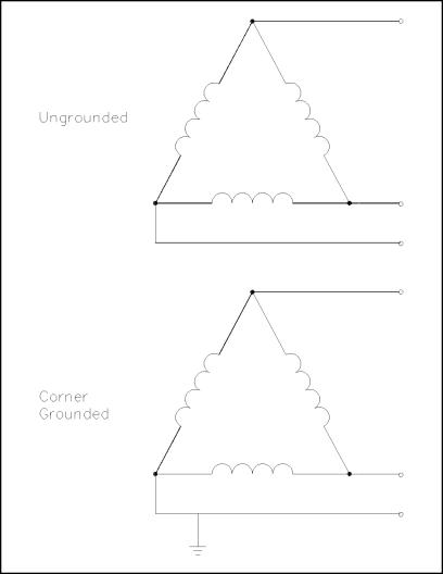
Wiring Schemes Unlike the single-phase wiring scheme that must make a provision for a neutral leg and separate ground, the three-phase system needs neither a separate neutral nor a ground to operate safely. However, to prevent any unsafe condition, all 3- and 4-wire, three-phase systems can include an effective ground path. As with the previous single-phase discussion, only the secondary side of the transformer and its connected load need to be studied. 3-Wire, Three-Phase Delta System The simplest three-phase system is the 3-wire Delta configuration, normally used for transmission of power in the intermediate voltage class from approximately 15,000 volts to 600 volts. The diagram in Figure 17 depicts the two methods of connecting the Delta secondary. The upper diagram depicts the ungrounded Delta, normally confined to protected environments such as fully enclosed ducts or overhead transmission lines that cannot be reached without extraordinary means. Each conductor's ground voltage is equal to the full phase voltage of the system. The lower diagram shows a ground point affixed to one corner of the Delta, which effectively lowers one phase's voltage reference to ground to zero, but retains a phase-tophase voltage potential. The corner-grounded phase acts in much the same way as the grounded neutral of the singlephase Edison system, carrying current and maintaining ground potential.
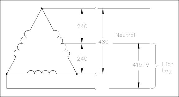
Figure 17 3-Wire, Three-Phase Delta Scheme The corner-grounded Delta system has an obvious economy in wiring costs, and the grounded phase can be used to physically protect the other two phases from accidental grounding or lightning strikes in outdoor settings. This system is rarely used for low voltage (under 600 V), however, because of the absence of a safety ground required by many facilities for circuits involving potential worker contact. 4-Wire, Three-Phase Delta System The 4-wire, three-phase Delta system combines the ungrounded Delta discussed above for threephase loads with the convenience of the Edison system for single-phase loads. As depicted in the example illustration in Figure 18, one side of the Delta has a grounded-neutral conductor connected to a center tap winding on one phase.
Figure 18 4-Wire Delta System The single-phase voltage on each side of the half-tap is one-half the voltage available in the normal phase-to-phase relationship. This provides the same half- or full-voltage arrangement seen in the normal Edison scheme with a grounded neutral. Notice also that the legs coming from the corners of the Delta would have a normal ungrounded appearance if it were not for the center tap of one phase. Thus, at any given location in the system, either three-phase power at full voltage or single-phase power with half or full voltage is equally possible. However, there are several strict precautions that must be observed in the operation of this system. First, all loads must be carefully balanced on both the single-phase and three-phase legs. Second, because the voltage between one leg and the grounded neutral is considerably higher than the rest of the single-phase system, a measurement between the neutral and the phase must be taken to identify the "high leg," or "bastard voltage." Last, the "high leg" is never used as a single-phase source because no ground or grounded neutral exists for this circuit.
|
||
|
||