
TM 11462525514/TO 33A1-13170-1
its effect on feedback, the bridge causes the
t h a t the tube essentially functions as a triode.
amplifier gain to be reduced for the frequency
Operating bias is produced by the voltage drop
being rejected (fo). Both phase and amplitude
across R37. Resistor R36 is the grid return. SET
characteristics combine to decrease the attenua-
LEVEL control R38 adjusts the feedback voltage
tion of other frequencies; therefore, the bridge, in
obtained at the cathode of V6 and returned to V2.
conjunction with the amplifiers, produces a much
This action provides gain control of the combina-
sharper frequency rejection curve than is obtained
tion of the preamplifier and bridge amplifier cir-
from the bridge alone.
c u i t s , when function switch S4 is set to SET
LEVEL.
65. Bridge Amplifier Circuit
6 6 . Function Switch S4 and dB Gain of
bridge amplifier circuit. Tube V5 is the phase am-
plifier for the bridge amplifier circuit. The input
Rotary switch S4A (fig. 6-7) has four switching
signal to tube V5 is obtained from the bridge and
p o s i t i o n s . The setting of this switch determines
is applied to both the control grid and the
the type of operation of the spectrum analyzer as
cathode. The grid connection to the input signal is
follows:
made to the junction of the series and shunt reac-
tive arms of the bridge through C32. The cathode
bridge, and bridge amplifier circuits are discon-
connection to the input signal is made to the junc-
nected from the vtvm circuit. In this position, in-
tion of the resistive arms of the bridge. At the re-
c o m i n g signals are connected to the METER
jection frequency of the bridge, no net signal volt-
binding posts, and the spectrum analyzer is
age appears at the input of V5.
o p e r a t e d as a standard vtvm.
b. Operating bias for V5 is produced by the
b. When S4A is set to DISTORTION, it in-
voltage drop across R33. Resistor R32 is the grid
serts the frequency selective amplifier ahead of
r e t u r n . Resistor R34 is the plate load. Resistor
the vtvm circuit. In this position, the fundamen-
R35 is the screen grid voltage dropping resistor.
tal frequency of the signal being measured is re-
Capacitor C15 bypasses the screen grid to ground.
jected by the bridge and only the remaining
harmonics pass through the bridge amplifier to
When switch S4A is set to SET LEVEL or
NOISE, V5 is converted to a grounded grid am-
the vtvm circuit.
c. When S4A is set to SET LEVEL it shorts
p l i f i e r . Under this condition, the reactive arms
the bridge circuit to ground so that the preampli-
there is no rejection frequency. The output of V5
fier and bridge amplifier circuits operate as a
straight five-tube amplifier with 20-dB gain. In
is passed through C16 to the control grid of V6.
this position, all incoming frequencies are passed
c. Cathode follower V6 is the output stage of
from the output of the bridge amplifier to the
t h e bridge amplifier. The screen grid and sup-
vtvm circuit.
pressor grid of V6 are connected at the plate so
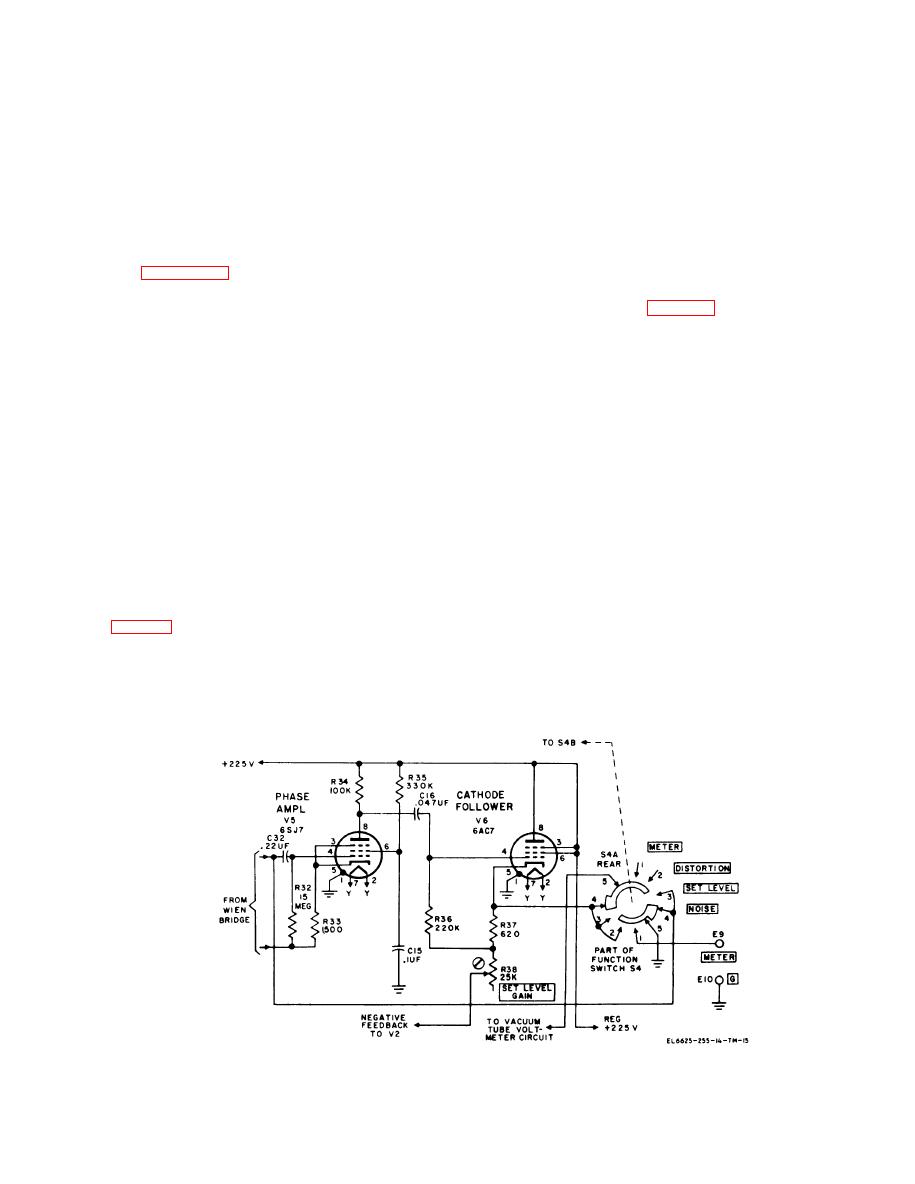
Figure 6-7. Bridge amplifier circuit, simplified schema tic diagram.
6-7

