
TB 9-6625-396-50
(6) Adjust L and G switches for a null indication on null detector.
CAUTION
Reduce audio oscillator amplitude to zero prior to changing
RANGE switch.
(7) Record L switch indications.
(8) Connect shorting bar between standard inductor terminals.
(9) Repeat (6) and (7) above.
(10) Subtract L switch indication recorded in (9) above from L switch indication
recorded in (7) above. The difference will be the actual inductance.
NOTE
If the calibration certificate stated accuracy for the inductance
standard exceeds 0.1 percent, the calibration certificate stated
accuracy must be used instead of the 0.1 percent as stated in
(11) and (13) below.
(11) If actual inductance is not within 0.1 percent of value listed on calibration
certificate supplied with standard inductor being measured, perform (b) below.
(12) Reduce audio oscillator amplitude to minimum.
(13) Repeat technique of (3) through (12) above for each standard inductor and
RANGE switch setting listed in table 4. Values obtained will be within 0.1 percent of value
listed on calibration certificate supplied with standard inductor being measured.
NOTE
When values obtained in (9) above are less than 0.01 percent of
standard inductor being measured, values may be disregarded
and (8) through (10) above omitted.
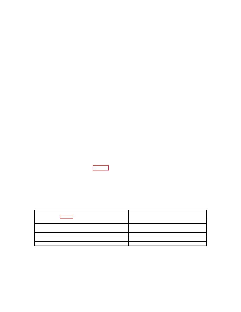
Table 4. Inductor Measurement
Standard inductor (nominal)
Test instrument RANGE
(see table 2 (A5a) through (A5F))
switch setting
a
100 H1
1 mH
c
10 mH
d
1H
f
10 H
g
2
10 H3
h
1For
RANGE switch setting a, the accuracy is 1 percent of value listed on calibration certificate.
2Connect
a 0.1 F capacitor in parallel across the TI external capacitor terminals.
3Connect a 0.5 F capacitor is parallel across the TI external capacitor terminals.
6

