ARMY TM 9-6115-464-12
AIR FORCE TO 35C2-3-445-1
NAVY NAVFAC P-8-624-12
NOTE
If the reverse power indicator (16) of either set illuminates and the main load contac-
tor opens, open the main power switch and reparallel the generator sets.
When generator sets are being operated in parallel, one or more operators
must remain with the sets to monitor the rated load and current meters.
Equipment damage could result if caution is not observed.
NOTE
Three generator sets can be operated in parallel. Paralleling procedures are the
same as those described above. One generator set at a time is brought on line.
Prior to removal of generator sets from parallel operation, make sure the load
does not exceed the full load rating of generation set(s) remaining on line,
Equipment damage could result if caution is not observed.
j.
To remove a generator set from parallel operation, place the circuit breaker switch of the set in the OPEN
position. Stop the set described in paragraph 2–7.
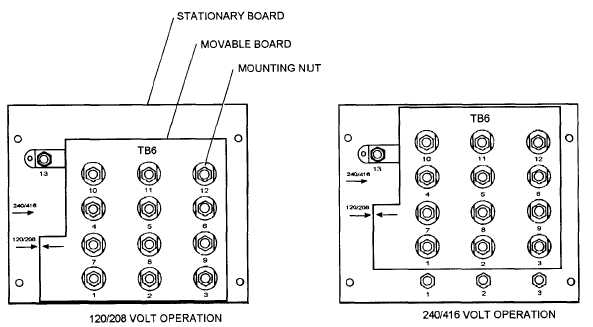
Figure 2-7. Voltage Reconnection Board
2-15