
TM 3-6665-302-34
(15) over tube coupling (13). Slide end of tub-
ing (12) over other end of tube coupling (13).
(3) Hold pin (30) away from rollers (31)
NOTE
and slide long tubing (15 ) through guide (18)
During scheduled servicing of pump as-
starting at coupling (13) side of guide.
sembly, replace tubing (15) and test
pump assembly (para 3-5 b).
fitting in head assembly (2). Slide tube coup-
a. Removal.
ling (13) into hole in guide (18).
(1) Remove cover (para 3-26a).
(5) Install cover (para 3-26 b).
(2) Detach tubing (12 and 15) from tube
coupling (13).
3-29. Tubing Guide
(3) Hold pin (30) away from rollers (31)
a. Removal.
and slide tubing (15 ) out of guide (18).
(1) Remove cover (para 3-26a).
(4) Remove other ends of tubing (12 or 15)
(2) Remove end of tubing (15, fig. 3-18)
from metal fittings in head assembly (2).
from coupling (13) and head assembly (2).
(5) Unscrew pin (30) counterclockwise
(3) Hold pin (30) away from rollers (31)
from top of guide (18).
and remove tubing (15) from guide (18).
b. Installation.
(4) Disconnect two springs (14) from guide
(1) Screw pin (30) clockwise into top of
(18).
guide (18).
(5) Unscrew and remove pin (30) from top
(2) Slide one end of replacement tubing
of guide (18).
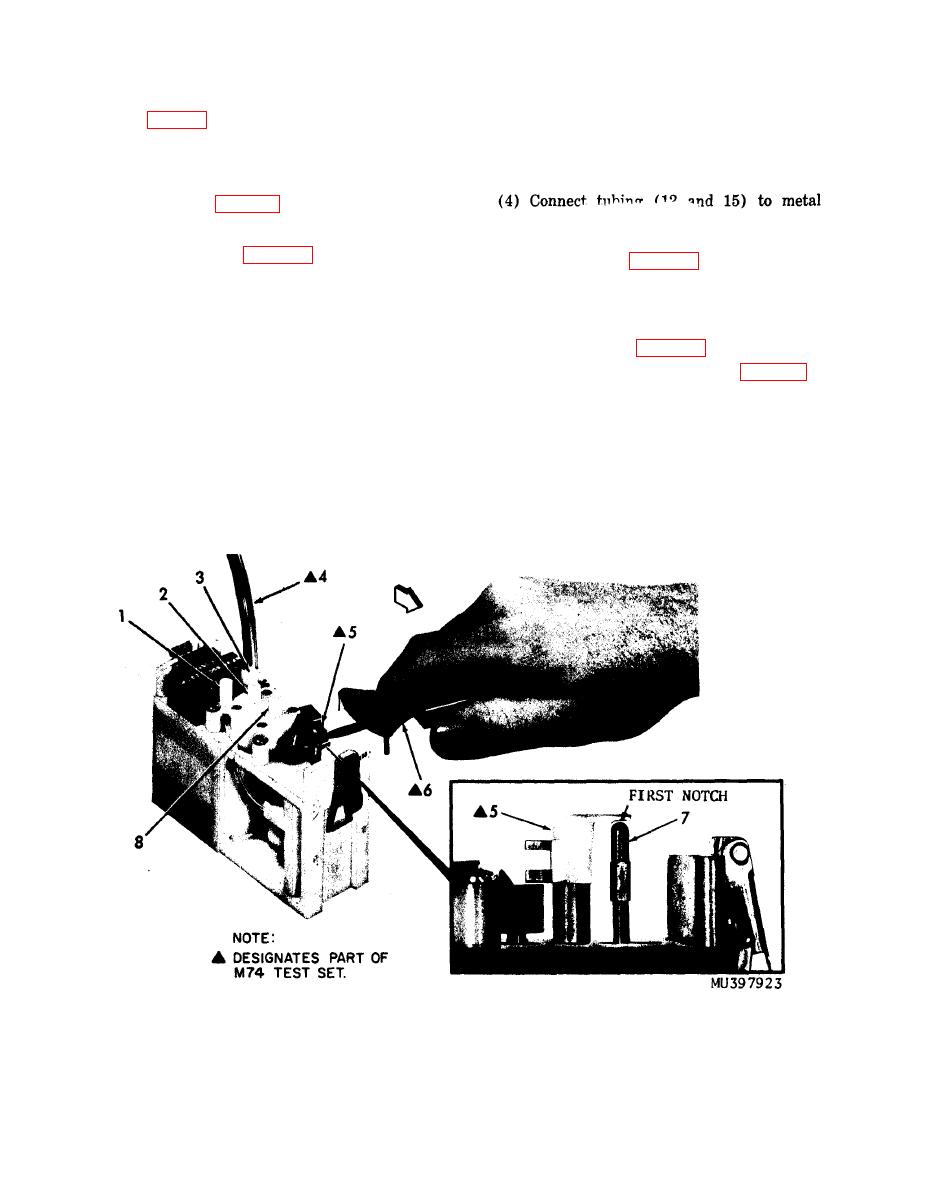
1 Fluid outlet port
4 PRESSURE TEST tube
7 Shoulder pin
2 Air inlet port
8 Air outlet port
5 Spring rate scale extension
3 Fluid inlet port
6 Spring rate scale
and pin height.

