Click here to make tpub.com your Home Page

Page Title: Figure 27. Pin Alignment and Valve
Back | Up | Next

Click here for thousands of PDF manuals

Google


Web
www.tpub.com

Home


Information Categories
.... Administration
Advancement
Aerographer
Automotive
Aviation
Construction
Diving
Draftsman
Engineering
Electronics
Food and Cooking
Logistics
Math
Medical
Music
Nuclear Fundamentals
Photography
Religion


Back
Figure 25. Hydraulic Controls and Clevis
Up
TM-9-2510-247-13-P Fifth Wheel Towing Device Model 250M (NSN 2510-01-458-8253) Manual
Next
Figure 29. Pin Alignment Items

TM 9-2510-247-13&P
0007 00
TRANSPORT CONFIGURATION - Continued
WARNING
DO NOT operate boom until mast is in track. Failure to comply could cause
serious injury or death to personnel or damage to equipment.
7. Main frame fifth wheel area should be clear of obstructions.
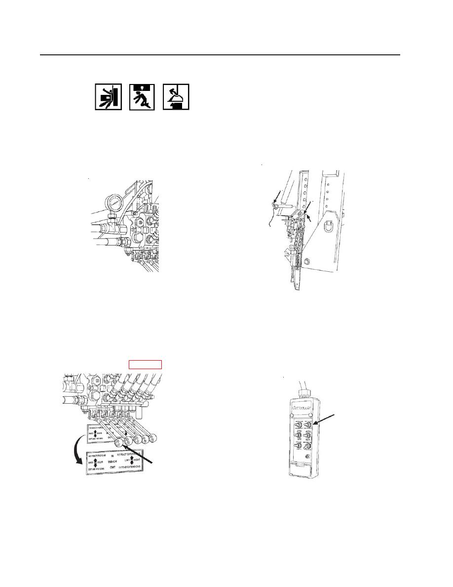
8. Insert pivot pins (17) into aligned holes (15 and 16).
17
15
16
Figure 27. Pin Alignment and Valve
9. Using remote control box or valve control levers, MAST RETRACT (18) to fold mast onto
main frame.
NOTE
Hydraulic pressure gauge should read 300-800 psi. If adjustment is needed,
refer to WP 0003.
18
18
Figure 28. Hydraulic Controls
10. Remove pivot pins (17).
0007 00-4

Privacy Statement - Press Release - Copyright Information. - Contact Us