Custom Search
|
|
 
|
||
|
LIGHTING INTENSITY CALCULATIONS Achieving the most satisfactory solution for any given lighting problem requires sound judgment in making necessary compromises of all factors involved. Selection of the luminaire can be influenced by budget constraints, present stock levels in the Federal Supply System, and availability. Once the luminaire is selected, it is important that you use the manufacturer's literature to determine the number of luminaires, mounting height, and spacing required to produce the desired illumination intensity. Using the manufacturer's literature supplied in figure 1-12, let's solve this sample problem: Find: 1. One-sided spacing required to provide specified illumination 2. Uniformity of illumination Given: (See fig. 1-14.) Street width, 50 feet Mounting height, 40 feet Pole setback from curb, 2 feet Bracket length, 12 feet Required average maintained level of illumination, 2 footcandles GE, 400-watt, LucaloxR luminaire (50,000 lamp lumens)
Figure 1-14.\Streetlight sample problem. Solution: 1. Spacing. The equation to determine correct spacing is
Where: LL = rated initial lamp lumens MF = maintenance factor CU = coefficient of utilization fc = illumination in footcandles W = street width, curb to curb The values are given for LL (50,000), MF (assume 0.70), W (50), and fc (2). After a value for CU is determined, you can solve the equation for average spacing. To determine the coefficient of utilization, it is necessary to calculate the amount of wasted light on the street side (SS) and the house side (HS) where:
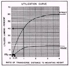
From the utilization curve in figure 1-15, the ratio of 1.0, street side, corresponds to 40 percent, and the ratio of 0.25, house side, corresponds to 3 percent, for a total of 43 percent CU. Spacing can be determined as
2. Uniformity. The uniformity of illumination is expressed in terms of a ratio of
It has been determined that one-side spacing of 150 feet will produce an average of 2 footcandles on the roadway surface. The point of minimum illumination can now be determined from the isofootcandle diagram. The minimum value of the illumination can be found by studying the isofootcandle diagram and taking into account all luminaires that are contributing significant amounts of light. Generally, the minimum value will be found along a line halfway between two consecutively spaced luminaires. This can be determined by checking
Figure 1-15.\Utilization curve.
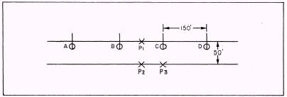
Figure 1-16.\Streetlight layout.
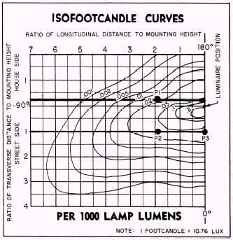
Figure 1-17.\Isofootcandle curve. the minimum footcandle values at points P1, P2, and P3, as shown in figure 1-16. The roadway surface can be plotted on the isofootcandle curve by observing the 40-foot mounting height to longitudinal and transverse distance ratios. (See fig. 1-17.) Since P1 is located outside the 0.02 footcandle line, it is the lowest total footcandle value. This value would be 0.03 fc (0.015 footcandle from each luminaire). Figure 1-18 shows a perspective view of the two isofootcandle lines that are considered when determining the illumination value at P1. The following factors are now applied to this "raw" footcandle value as shown in the formula: fc min = (fc) (LF) (MF) (CF) Where: fc min = minimum point footcandles fc = raw footcandle from isofootcandle diagram LF = lamp factor MF = maintenance factor CF = mounting height correction factor The values are given for fc (0.03) and MF (assume 0.70). The value for LF was determined earlier as 50 for the GE, 400-watt, LucaloxR lamp. The CF factor can be determined from the correction chart below the isofootcandle curve in figure 1-12. 'The CF for a 40-foot mounting height is 0.56. The minimum point footcandles are fc min= (0.03) (50) (0.70) (0.56) = 0.58 Therefore, the average-to-minimum ratio of uniformity would be
A uniformity ratio of 3.4 meets the ANSVIES recommended roadway illumination levels (table 1-2) for a major, commercial roadway. There are a number of charts and illustrations together with typical examples dealing with roadway complexities that require special considerations, such as intersections, interchanges, curves, hills, underpasses, railroad crossings, and many others. Helpful information in this area may be obtained from the IES Lighting Handbook. |
||
|
||