Custom Search
|
|
 
|
||
|
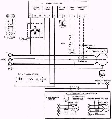
PARALLEL COMPENSATION (REAC-TIVE DROOP).\When parallel operation is required, additional components are required in the regulating system. These are resistor R25, transformer T3, and current transformer CT1. Two of the components are included in a parallelequipped voltage regulator. These are R25 and T3. Current transformer CT1 is a separate item and must be interconnected, as shown in figure 4-11. These components allow the paralleled generators to share the reactive load and reduce circulating reactive currents between them. This is accomplished in the following manner. A current transformer CT1 is installed in phase B of each generator. It develops a signal that is proportional in amplitude and phase to the line current. This current signal develops a voltage across resistor R25 (fig. 4-10). A slider on R25 supplies a part of this voltage to the primary of transformer T3. The secondaries of T3 are connected in series with the leads from the secondary of sensing transformer T1 and the sensing rectifiers located on the printed circuit board. The ac voltage applied to the sensing rectifier bridge is the vector sum of the steppeddown sensing voltage (terminals El and E3) and the parallel CT signal supplied through T3 (terminals 1 and 2). The regulator input sensing voltage (terminals E1 and E3) and the parallel compensation signal (terminals 1 and 2) must be connected to the generator system so as to provide the correct phase and polarity relationship. Regulators with single-phase sensing provide about 8 percent maximum droop while threephase-sensing regulators provide 6 percent droop. When generators are paralleled to the same bus and have different types of sensing, care must be taken to compensate for these differences using the slide wire adjustment on droop resistor R25. When a resistive load (unity power factor) is applied to the generator, the voltage that appears'
Figure 4-11.\Parallel compensation interconnection diagram. across R25 (and T3 windings) leads the sensing voltage by 90 degrees, and the vector sum of the two voltages is nearly the same as the original sensing voltage; consequently, almost no change occurs in generator output voltage. When an inductive load (lagging power factor) is applied to the generator, the voltage that appears across R25 becomes more in phase with the sensing voltage, and the combined vectors of the two voltages result in a larger voltage being applied to the sensing rectifiers. Since the action of the regulator is to maintain a constant voltage at the sensing rectifiers, the regulator reacts by decreasing the generator output voltage. When a leading power factor (capacitive) load is applied to the generator, the voltage across R25 becomes out of phase with the sensing voltage. The combined vectors of the two voltages result
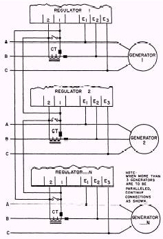
in a smaller voltage being applied to the sensing rectifiers. Then the regulator reacts by increasing the generator voltage. When two generators are operating in parallel, if the field excitation on one generator should become excessive and cause a circulating current to flow between generators, this current will appear as a lagging power factor (inductive load) to the generator with excessive field current and a leading power factor (capacitive load) to the other. The parallel compensation circuit will cause the voltage regulator to decrease the field excitation on the generator with the lagging power factor and increase the field excitation on the generator with the leading power factor so as to minimize the circulating currents between the generators. This action and circuitry is called reactive droop compensation (droop). It allows two or more paralleled generators to share inductive loads proportionally by causing a decrease or droop in the generator system voltage. REACTIVE DIFFERENTIAL COMPENSA-TION (CROSSCURRENT).\Reactive differential compensation allows two or more paralleled generators to share inductive reactive loads with no decrease or droop in the generator system output voltage. This is accomplished by the action and circuitry described previously for reactive droop compensation and by the addition of cross-connecting leads between the parallel CT secondaries, as shown in figure 4-12. When the finish of one parallel CT is connected to the start of another, a closed series loop is formed. This loop interconnects the CTs of all generators to be paralleled. The signals from the interconnected CTs cancel each other when the line currents are proportional and in phase. No system voltage decrease occurs. These regulators provide the necessary circuit isolation so that parallel reactive differential compensation can be used. THE REACTIVE DIFFERENTIAL CIRCUIT CAN BE USED ONLY WHEN ALL THE GEN-ERATORS CONNECTED IN PARALLEL HAVE IDENTICAL PARALLELING CIRCUITS INCLUDED IN THE LOOP. REACTIVE DIFFERENTIAL COMPEN-SATION CANNOT BE USED WHEN PARALLELED WITH THE UTILITY OR OTHER INFINITE (UTILITY) BUS.
Figure 4-12.\Crosscurrent compensation interconnection diagram.
|
||
|
||