Custom Search
|
|
  |
|
|
Clothes Dryers An electric clothes dryer is not as complicated as a washing machine; therefore, we will not go into as much detail on its operation as we did with the washing machine. The main electrical parts of a dryer are as follows: electric-heating elements, thermostats to control heat, a motor to turn the drum assembly, and a timer to select cycle operations. Most dryers have a cutoff switch on the door that stops the dryer when the door is opened. Many dryers have a 40-watt ozone bulb to help condition the air. This bulb requires either a ballast coil or a ballast bulb. Both high-limit and low-limit operating thermostats are used in dryers to control the air temperatures that pass through the clothes. These are located in the exhaust housing and can be easily checked during operation by a voltage check. Your tester will indicate a voltage each time the contact is opened. Safety thermostats should show continuity between terminals at normal room temperature. Holding a small flame close to the thermostat should cause it to open, indicating an open circuit across its contacts. Dryer timers are fairly simple to troubleshoot. Some timer drive motors and switching mechanisms can be replaced, but in most cases, it is more practical to replace the timer. Again, before attempting any repair or replacement of any parts, run the dryer through its cycles, eliminating any guesswork. Always refer to the wiring diagram for the particular dryer on which you are working. Figure 7-4 is a wiring diagram for a typical electric dryer. Electric Ranges Electric ranges cook food by surface-and oven-heating elements. The surface elements, or burners, are on the top of the range, and the oven elements are within the oven. Electric ranges differ in size, but most standard ranges have four surface burners, a deep-well cooker, and an oven. Electric ranges vary in width from the 20-inch apartment size to the 40-inch full-size range. The approximate height of the surface burners from the floor is 35 inches. The primary components of an electric range are the surface burners, deep-well cooker, oven, timer, and individual switches that control the temperatures of the heating units. The range usually has a convenience
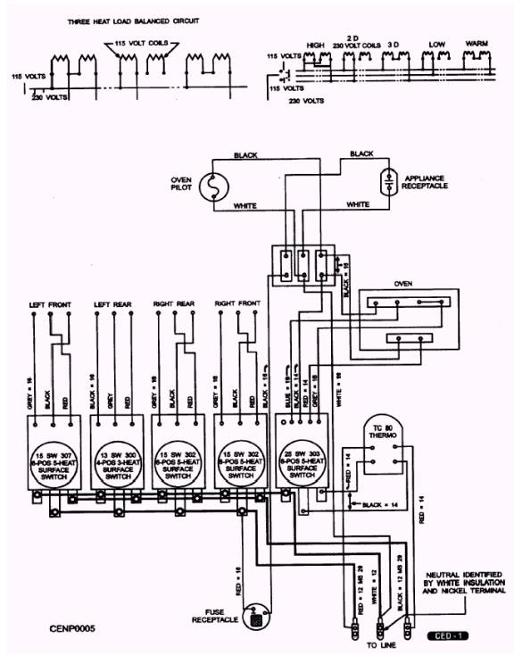
Figure 7-4.- Schematic of an automatic dryer. outlet to supply electricity for a coffee percolator, waffle iron, or toaster, which you can operate on the top of the range. The range is usually automatic. The oven control keeps the temperature of the oven at a set point, and an electric clock and timer shut off the oven at a predetermined time. The individual switches that control the temperatures of the surface burners are usually located on the front of the range. The principle of operation of an electric range is simply that of an electric current passing through a resistance, thereby producing heat. The resistance is usually nichrome wire. Heating elements used in ranges may be of the open or the enclosed types. The surface burners usually have enclosed tubular or cast-in elements. Each element is controlled by an individual switch that can control the element for as many as 10 different heat positions. The electrical power supply to each element is either 120 volts or 240 volts or both, depending upon the heat position of the switch Each surface burner is connected to a signal light that indicates when the unit is in the ON position. In the wiring schematic shown in figure 7-5, you can see the wiring of a typical electric range.
Figure 7-5.- Typical electric range wiring schematic.
|
|
|
|