Custom Search
|
|
  |
|
|
Constant-Current Transformer The constant-current transformer, usually called a regulator, has a movable secondary winding that automatically changes position to provide constant current for any load within its full-load rating. The balance point between coil weight and magnetic force may be adjusted to provide the desired output current. A moving-coil regulator is recommended because of the close regulation required for streetlighting work. It consists of a fixed primary coil and a movable secondary coil on a laminated core. Voltage applied to the primary winding causes voltage to be induced in the secondary winding. When the secondary circuit is closed, the magnetic field in the secondary reacts with the primary-coil field to push the movable coil up. The balance point between coil weight and magnetic force is designed to provide the desired secondary current (usually 6.6 amperes). On most existing installations, the constant-current regulator is of the outdoor type. Three main types of installation are used for these regulators: two-pole platform, timber or steel construction single-pole platform, and pole mounted. Any regulator larger than 20 kilovolt amperes should be mounted on a platform. Constant-current regulators should be loaded as near 100 percent as possible since both efficiency and power factor are best at this load. Specifications of the American Institute of Electrical Engineers (AIEE) require constant-current transformers to deliver the rated secondary current at lo-percent overload. A larger size regulator should not be installed before this 10-percent overload is reached. When larger regulators must be installed and are not readily available, a booster transformer may be used with its secondaries connected into the series street circuit and its primaries connected to the primary feeder supplying the regulator (fig. 6-20). secondary bushings insulated for the high voltage of the necessitates removing any internal lead connecting the series street circuit, a special booster transformer is two coils. The additional load handled by this device preferred to an ordinary distribution transformer for use equals the product of the street-circuit current and the with constant-current regulators of 10 kilowatts and secondary voltage of the transformer. Thus, if a larger. In using a booster transformer, the primary coil 2,400/ 240-volt transformer is used, the additional load Since transformers used for this purpose should have must be isolated from the secondary coil that
Figure 6-21.- Approximate lamp capacity for street-lighting regulators.
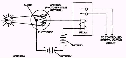
Figure 6-22.- Photoelectric cell control circuit. that the street circuit can carry is 240 volts times 6.6 amperes or 1.584 kilowatts. Figure 6-21 shows the maximum number of series lamps in the various sizes that may be used for full-load rating on a regulator. The average number of watts of energy consumption for each size lamp may be computed since the regulator ratings are based on their output. In this manner, the load of a circuit consisting of different size lamps may be computed. Example: What size regulator would be required to supply the following lamps? 25- 1,000-lumen, 6.6-ampere, straight-series lamps 50- 2,500-lumen, 6.6-ampere, straight-series lamps 10- 6,000-lumen, 20-ampere lamps with isolating transformer Solution: Figure 6-21 shows that the average energy consumption of a 1,000-lumen, 6.6-ampere, straight-series lamp with film cutout is 69 watts per lamp. In a similar manner, the average energy consumption of a 2,500-lumen lamp is 167 watts, and a 6,000-lumen, 20-ampere lamp with isolating
Figure 6-23.- Cadmium-sulfide cell control circuit, transformer is 405 watts. Totaling the combined load shows the following: 25 x 69 = 1,725 watts 50 x 167 = 8,350 watts 10 x 405 = 4,050 watts 14,125 watts or 14.1 kilowatts Therefore, a 15-kilowatt regulator would be required. NOTE: The table makes allowances for line losses in the average series street circuits. Control Circuits Several methods are used to control the operation of area lighting systems. For recreational lighting, only a manual switch is required. On the other hand, streetlights and security lights have more sophisticated controls. Lights normally are on during the hours of darkness or when unusual weather conditions indicate the need for artificial light. Although lights could be activated by assigning an individual to operate the controls manually, they are usually turned on and off by a combination of controls. Most control circuits that you will encounter in the field use one of the following devices to control the lighting system: photoelectric cell (fig. 6-22), cadmium-sulfide cell (fig. 6-23), time clock, pilot wire relay (fig. 6-24), or cascading relays (fig. 6-25).
Figure 6-24.- Pilot wire control of multiple-lighting circuits supplied from several feeder transformers.
Figure 6-25.- Cascade control of multiple-lighting circuits supplied from several feeder transformers.
|
 
|
|
|