Custom Search
|
|
  |
|
|
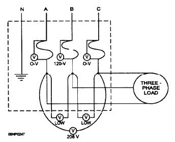
METERS Many times a visual inspection does not uncover an apparent problem; therefore, you must advance to troubleshooting with meters. In electrical troubleshooting, you will use voltmeters, ohmmeters, ammeters, and the meter that incorporates many meters- the multimeter. When using a voltmeter, you have to connect the power to the circuit before testing. On the other hand, you cannot use the ohmmeter on an energized circuit. You need to start voltmeter tests at the power input end of the circuit, whereas you start ohmmeter tests at the ground end Electrical circuit troubles develop either in the wiring or in the operating unit. If you analyze the problem carefully and take systematic steps to locate it, not only will you save much time and energy, but you will also prevent damage to expensive equipment. Either dead circuits or live circuits can be tested with instruments. Circuit defects can sometimes be located more easily by one method than the other, depending upon the type of circuit and the trouble. To test a dead circuit, disconnect the device from the outlet or disconnect switch. Equipment for this method of testing includes such units as ohmmeters and battery-powered test lamps. Asuitable continuity tester can be made easily from a flashlight in an emergency. An ohmmeter that contains its own batteries is excellent for continuity testing. A basic factor to consider in choosing continuity test equipment is to use relatively low-voltage instruments, reducing the danger of sparking. WARNING When connections are made in the presence of combustible vapors, sparking is a serious fire hazard. When you test live circuits, energize the circuit under test from the power source. Generally, you will test with a voltmeter. Make certain that the voltmeter is designed for the type of current to be tested and has a scale of adequate range. Ensure that the circuit is disconnected from the power source before making the necessary circuit changes; then reapply the power. WARNING Be extremely careful not to touch the hot conductors when you use this method of testing because these live points of the circuit are exposed when the junction box covers are removed. Let us troubleshoot a circuit with a voltmeter. The power to the circuit must be turned on. The first and most logical place to check is the fuse or circuit breaker panel. Set the voltmeter to the proper scale. If you do not know the value of the incoming voltage, set the meter to the highest scale; then work down to the proper scale. Check each incoming phase by connecting one lead of the voltmeter to the neutral and the other to each phase separately. On a three-phase 120/ 208, 240-volt service, you must get 120 volts on each phase to ground. Less than 120 volts on one phase means that phase is open and you are getting a feedback from equipment connected to the lead side of the panel. Sometimes there will be a slight variation of normal voltage from the different phases; therefore, to determine if one phase is dead, check between the phases. To perform this test, place one lead of the voltmeter on Phase A and the second lead on Phase B and read the voltage. It should read approximately 208 or 240, depending upon the system. After you have taken this reading, move the second lead to Phase C and take the reading. After this reading, move the first lead to Phase B and take the reading. You have now read between all phases and a lower than normal reading indicates an open phase. Which phase is dead? Assume that Phase B has a blown fuse. When you take your reading between Phases A and B (fig. 5-69). you get a low-voltage reading. Your next reading, between Phases A and C, reads normal. But the next reading, between Phases B and C, again is a low reading. Each time you read to Phase B, you get low voltage. This reading is a good indication that Phase B is open. Another way to determine which phase is open is to place one voltmeter lead on the top of the fuse and the other lead on the bottom of the same fuse. If you get a voltage reading across the fuse, that fuse is open.
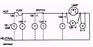
Figure 5-69.- Checking a three-phase circuit for a blown fuse. Assuming that everything is all right at the main panel, let us examine a single 120-volt circuit. Illustrations help explain the procedure for locating an open in a circuit. Figure 5-70 shows a circuit with a lamp in series with a single-throw switch and fuse and the normal voltage readings at the various points of the circuit. If the lamp fails to light, check the circuit in progressive steps through the circuit and lamp from the last point where voltage is known to be present. In figure 5-71, we have voltage at one connection of the
Figure 5-70.- Circuit with fuse, switch, and lamp.
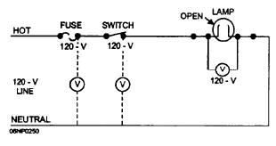
Figure 5-71.- Circuit with blown fuse.
Figure 5-72.- Circuit with burned-out lamp. fuse and no voltage at the other. Since the fuse is a conducting unit. normally the same voltage reading should occur between both sides of the fuse and the ground. The only conclusion in this case, then, is that the fuse is open. Figure 5-72 shows that there is a voltage reading when the voltmeter is connected across the lamp. The logical assumption is that the lamp is inoperative. To be sure the lamp is inoperative, you must check it with an ohmmeter. Fuses, switches, and lamps are vulnerable; and you should check them first in a circuit. In figure 5-73. the lamp does not light and the voltmeter shows voltage from the ground screw of the lamp to the neutral wire. These conditions indicate an open in the ground wire. When you connect the voltmeter at another point at the right of the lamp and no voltage is indicated, you can assume that there is an open in the wiring between this point and the lamp connection. In figure 5-74, you find two lamps wired in parallel so that they can be controlled by a double-throw switch. With the switch in the OFF (center) position, there is no complete circuit, and neither lamp lights. When the switch is in the BRIGHT position, a circuit is completed through the switch and through both lamps. With the switch in this position, the only resistance in the circuit is the resistance of the lamps. When the switch is in the DIM position, the circuit is completed through the lamps as before; but this circuit has an additional resistor in series with the lamps. This added resistance causes a decrease in current flow; therefore, the lamps glow with less intensity than before. If one of the lamps lights and the other one does not, it is not necessary to check the complete circuit to find the open. The part of the circuit up to Point A is common to both lamps, and that much of the circuit must be completed for even one lamp to light. The place to begin checking the circuit is after Point A in the affected part of the circuit. In a circuit, such as the one shown in figure 5-74, it is best to use a voltmeter to locate the trouble. If you connect the negative lead of the voltmeter to the ground and the positive lead to Point A, you will get a reading on the voltmeter scale because Point A is connected through the switch to the positive line wire. If the positive lead of the voltmeter is moved in succession from A to B to C, you are able to check the continuity of wires AB and BC. If the check at Point C reveals no voltage, this condition indicates that wire BC is open. You can make this same check with an ohmmeter, but several additional steps are required. First, remove power from the circuit by placing the circuit breaker and circuit switch in the OFF position. Next, disconnect the junction of wires at Points A and C. Then, with one ohmmeter lead placed on the loose wire at A and the other one on B, check the continuity of the wire. When this check is made and the ohmmeter indicates a low resistance, you have continuity in the wire. But if you place one ohmmeter lead on B and the other on the disconnected wire at C and you get an infinite resistance, there is an open in the wire.
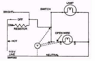
Figure 5-73.- Circuit with open in the wiring.
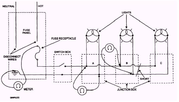
Figure 5-74.- Troubleshooting an open circuit with a voltmeter. WARNING For your safety, before you begin testing with an ohmmeter, BE SURE that the circuit that you are about to test is de-energized. Isolate the circuit being tested to prevent reading resistance from other circuits. Many times you can determine the approximate location of an open by simply studying the circuit diagram before doing any actual circuit testing. For example, suppose both lamps in figure 5-74 light when the circuit switch is placed in the BRIGHT position, but neither lamp lights when the switch is placed in the DIM position. Because the lamps light when the switch is in one position, you can gather that all wires and lamps are good. The only units that could be faulty are the resistor, half of the switch, or the wires that connect the switch and the resistor. By using the ohmmeter as you did before, you can check the continuity of these parts. A short circuit exists when there is a direct connection between two wires or conductors of different potentials. If the trouble is not found by a visual inspection, you must isolate it step by step. First, disconnect all the equipment in the circuit and install a new fuse or place the circuit breaker to the ON position. If the short is clear, then the trouble will be found in the equipment. However, if the short circuit does not clear and the fuse burns out again or the circuit breaker trips, then the trouble is in the wiring. To find the short in the electrical wiring, you first disconnect the wires at both ends of the circuit and test each wire with an ohmmeter. If there is a short between the wires, a low-resistance reading will appear on the ohmmeter. If no short exists between the wires, a high-resistance reading will appear on the ohmmeter. You should continue this procedure until the short is found. Let us assume that a light circuit is faulty. Using figure 5-75 as an example, you see a circuit with three lights controlled by a switch with a short at the junction box of the middle lamp. Disconnect the wires at the fuse panel to isolate the circuit and to prevent feedback from the other circuits. Connect one lead of the ohmmeter to neutral and the other to the wire you have just disconnected. With the switch open, the ohmmeter will read infinity. Closing the switch will cause the ohmmeter to read continuity, showing that the short is beyond the switch. You can now proceed to the nearest junction box and test at the first light. Remove all light bulbs from the circuit. Disconnect Point A and connect the ohmmeter between the neutral and the wire leading to the first
Figure 5-75.- Faulty lighting circuit. lamp. You will read infinity. Remember, "infinity" means that the circuit is good, and "continuity" means a short. Now, connect the ohmmeter between the neutral and the lead going to the middle lamp. The reading will show continuity, indicating the short is beyond Point A. You should leave Point A open at this time and continue on to the middle lamp. Disconnect Point B and take the same readings that you took at the first light. From these tests you can determine that the circuit between the first and middle lamp is all right (infinity reading), and the trouble must be between the second and third lamp. By checking closely at the middle junction box, you can probably see charred or frayed wires indicating the problem. You may need to continue your check to Point C. Use the same procedure as with the other lamp, and find the trouble between Points A and C.
|
 
|
|
|