Custom Search
|
|
  |
|
|
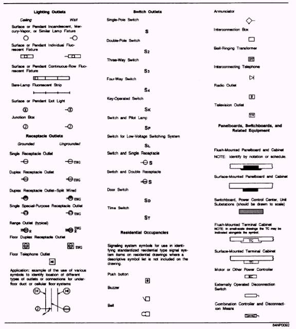
DRAWINGS AND SKETCHES As a Construction Electrician you will be required to read and interpret drawings and specifications, sketches, and electrical diagrams. Before you can work with drawings effectively, you must know how to interpret electrical symbols correctly. Knowing how to draw and interpret freehand sketches is also important. You will see how the different parts of a drawing relate to the overall plan the drawing represents. You will also learn to recognize the different types of drawings and their uses. SYMBOLS One of the most important symbols to use right at the beginning of a new job is the directional symbol. This symbol, which is usually an arrow labeled "N" for north, enables the reader of a construction drawing to orient it. A drawing is properly oriented when it is held so that the north arrow shown on the drawing is pointing toward north. Construction Electricians sometimes find themselves standing in open ground with only a drawing and an area staked off by the Engineering Aid who tells them where to start shoveling for an underground conduit run. The drawing must be properly oriented so the reader can relate the information on it to the surrounding area. Understanding common standard symbols, such as the north arrow mentioned above, is a must for some one who expects to do well inelectrical construction work. Some of the most common symbols you will see in building construction work are listed in figure 2-5. These symbols were selected from ANSI Y32.9- 1972. Study these symbols carefully. A good way to memorize them is to copy each symbol several times while thinking of the electrical component or device it represents. Learn to relate each symbol mentally to the component it represents whenever you see the component. For example, as you pull the wire through a conduit in a floor slab, you might try to recall the symbol mentally for "wiring concealed in floor." When you walk into the company office and see a duplex receptacle outlet, you should think about its symbol. This practice will enable you to associate symbols to actual electrical devices. This type of training will help you become a better CE. Although figure 2-5 shows some of the most common standard symbols, these are by no means the only ones you will see in your work. Sometimes a symbol for a particular component or device may have been created by the architect or engineer who developed the drawing. For various reasons, some of the symbols on a drawing may not be standard. Many times you will figure out what a symbol means by analyzing it and thinking about what it looks like. The legend on a drawing should show any nonstandard symbols and their meanings.
Figure 2-5.- Graphic symbols used in building construction
Figure 2-5.- Graphic symbols used in building construction- Continued.
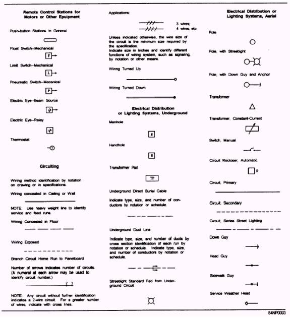
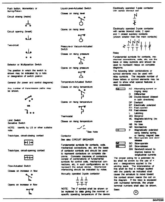
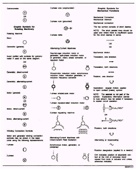
Figure 2-6 shows some more standard electrical symbols. They may also be used in construction drawings but will most often be seen in other types of drawings, such as schematic diagrams. The symbols in figure 2-6 were selected from ANSI Y32.2-1975. This standard gives the following information about the symbols that may help you understand them better: Graphic symbols are used to show the functioning or interconnections of a circuit graphically.
Figure 2-6.- Graphic symbols used in electrical and electronic diagrams. 2-9 43
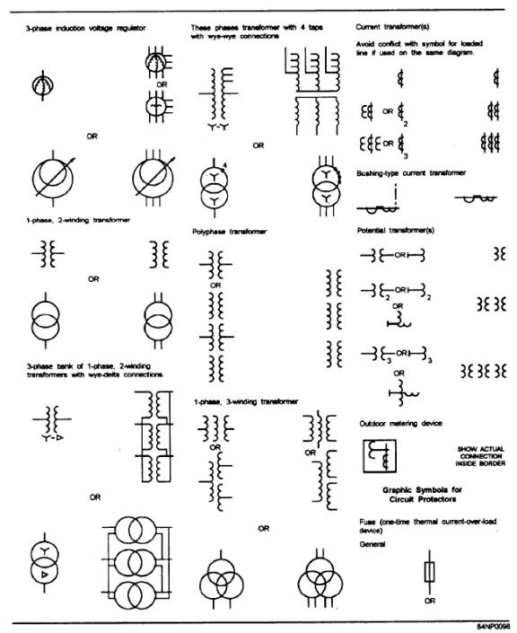
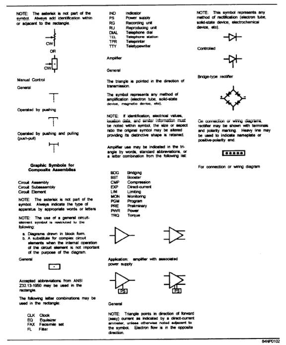
Figure 2-6.- Graphic symbols used in electrical and electronic diagrams- Continued.
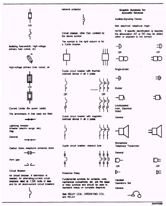
Figure 2-6.- Graphic symbols used in electrical and electronic diagrams- Continued.
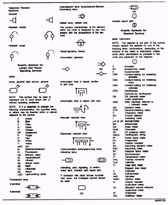
Figure 2-6.- Graphic symbols used in electrical and electronic diagrams- Continued.
Figure 2-6.- Graphic symbols used in electrical and electronic diagrams- Continued.
Figure 2-6.- Graphic symbols used in electrical and electronic diagrams- Continued.
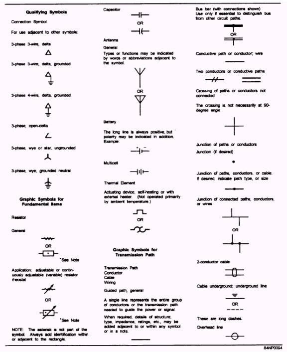
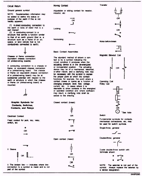
Figure 2-6.- Graphic symbols used in electrical and electronic diagrams- Continued. A graphic symbol represents the function of a part in the circuit. Qualifying symbols may be added to symbols when the special characteristic is important to the function of the device and aids in the understanding of the overall function performed. For example, connection symbols shown in column 1 of figure 2-6 are headed "Qualifying Symbols." They are combined with transformer symbols shown further on in the figure. Some symbols may be similar or identical to other symbols but have different meanings. Only one meaning will apply to a specific symbol used on a diagram. Notes, asterisks, and flagging techniques may be used with symbols having multiple meanings. A tabulation listing the intended meanings should be provided. Except where noted, the orientation of a symbol on a drawing does not alter the meaning of the symbol.
|
 |
|
|