Custom Search
|
|
  |
|
|
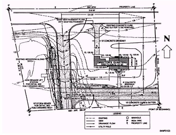
FREEHAND SKETCHES When installing electrical systems and circuits, you will sometimes have to exchange information about your job with others. A freehand sketch can be an accurate and a concise way to communicate this information. This type of drawing is informal in character, may or may not be drawn to scale, and need not follow any particular format. A sketch can be used in many ways. One example of where to use a sketch is to show a field change that must be made. Nomatterhowwellaproject is planned, occasionally field changes have to be made. You may see that a field change is necessary because a conduit run cannot practically be routed according to the approved drawing or plan. You can make a freehand sketch showing only what has to be changed. The sketch may include dimensions, symbols, and other information needed to convey your idea of the required change to someone else (like the project supervisor or project chief). TYPES OF DRAWINGS AND DIAGRAMS The types of drawings to be discussed here include working drawings, architectural drawings, mechanical drawings, shop drawings, and electrical diagrams. CONSTRUCTION DRAWINGS A construction drawing is any drawing that furnishes the information required by the craftsmen to rough in equipment or erect a structure. The terms working drawings and construction drawings are sometimes used interchangeably. Information presented in a set of working drawings, along with the specifications, should be complete so the craftsman who uses them will require no further information. Working drawings show the size, quantity, location, and relationship of the building parts. Generally, working drawings may be divided into three main categories: architectural, mechanical, and electrical. Regardless of the category, working drawings serve several functions: They provide a basis for making material, labor, and equipment estimates before construction starts. They give instructions for construction, showing the sixes and location of the various parts. They provide a means of coordination between the different ratings. They complement the specifications; one source of information is incomplete without the other when drawings are used for construction work. Architectural Drawings Architectural drawings consist of all the drawings that describe the structural members of the building and their relationship to each other. This includes foundation plans, floor plans, framing plans, elevations, sections, details, schedules, and bills of materials. Plans A plan is actually a part of the architectural drawing that represents a view of the project from above. Two types of plans will be discussed here: plot plans and floor plans. PLOT PLANS.- A plot plan (also called a site plan) includes not only the project but also the surrounding area. The project may be represented only by an outline, such as the Director's Quarters project on the plot plan in figure 2-7. The grades at fixed points are shown throughout the area. This is done to show how the land slopes before construction is started and the finished grade after construction is completed. The north arrow symbol, used for orientation of the drawing, is shown. The Construction Electrician may have to have a plot plan to construct a pole line to the project site at or near the earliest phase of construction. Another example is when the slope and grade of the surrounding area is to be changed and you have to bury cable or conduit. You must know what the finished grade is and how deep to dig. This type of work requires close coordination between you, the Engineering Aids, Equipment Operators, and Builders. By looking over the plot plan, you will know what to do to prepare for the job.
Figure 2-7.- Plot plan including "Director's Quarters" project.
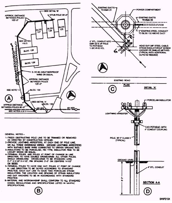
Figure 2-8.- Plot plan with electrical layout, general notes, detail, and section drawings. Another type of plot plan can be seen in figure 2-8. Figure 2-8, view A, shows five buildings that are to be supplied with electricity for power and lighting. An electrical layout has been superimposed on the plot plan General notes (fig. 2-8, view B), one detail (fig. 2-8, view C), and section A-A (fig. 2-8, view D) of that detail are shown The dotted line at the bottom of the page indicates underground ducts containing previously laid cable. The design engineer has decided to tap the cable at manhole 22 and run lines overhead to dead-end at the rear of building 126. Figure 2-8, view C, shows that lines are to be run underground from manhole 22 to the first pole crossarms. At building 126, lines are to be carried down the pole, regathered through a pothead into the conduit again, and run underground to a concrete slab, and out through another pothead to a transformer bank. Where do you get this information? Refer to figure 2-9. Figure 2-9 shows detail B is indicated in figure 2-8, view A. This represents the installation behind building 126 where the overhead line terminates. The last pole in the system is shown in the lower left comer. From the pole to the transformer bank, the underground conduit is indicated by dotted lines. The conduit runs underground to the concrete slab on which the transformers rest. Section A-A gives construction details of the slab.
|
 
|
|
|