Custom Search
|
|
  |
|
|
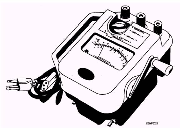
Amperage Measurements It is possible that you may never use a multimeter for amperage measurements. Most multimeters are designed with quite low current ranges. The clamp-on ammeter (discussed earlier) is the most convenient portable instrument for measuring ac amperes. Resistance Measurements 7-22 As mentioned earlier, ohmmeters have their own voltage source. This circumstance is also true of the ohmmeter function of multimeters. The size and number of batteries for different instruments vary. Usually one or more 1 1/ 2-to 9-volt batteries are used for resistance measurements. As you must set up the meter to measure voltage accurately, so you must set it up for measuring resistance. If you are to measure a 120-ohms resistor, for example, set the selector switch to ohms at the appropriate range. For the analog instruments, set the switch to the R x 1 or x 1 as appropriate. Read the value from the ohms scale directly. For higher values of resistance like 1,500 ohms, for example, use the R x 100 or x 100 range. In this case, multiply the reading from the ohms scale by 100. For all critical resistance measurements, always touch the leads together and set the indicator needle to zero with the appropriate adjustment knob. Do not let the leads touch your fingers or anything else while you are zeroing the meter. On multimeters, use the common - (negative) and + (positive) jacks for resistance measurements. Be certain that there is no power on the circuit or component you are to test when measuring resistance. Be sure also to discharge any capacitors associated with the circuit or component to be tested before connecting the instrument to the circuit or component For critical measurements, make sure that only the circuit or component you are to test touches the leads while you take the reading; otherwise, the reading may be inaccurate, especially on the higher resistance ranges. Many times you will use the ohmmeter for continuity tests. All you will want to know is whether the circuit is complete or not. You will not have to zero the meter for noncritical continuity tests. You will want to touch the leads together to see where the needle comes to rest. If the needle stops at the same place when you place the leads across the circuit, you will know the path has a low resistance. In other words you will know there is continuity through the circuit. Construction Electricians also use other instruments for different types of resistance measurements. We will discuss these instruments next. MEGOHMMETERS The megohmmeter is a portable instrument consisting of an indicating ohmmeter and a source of dc voltage. The dc source can be a hand-cranked generator, a motor-driven generator, a battery-supplied power pack, or rectified dc. The megohmmeter is commonly called a "megger" although Megger(c) is a registered trademark. The megger tester shown in figure 7-25 is an example of a dual-operated megohmmeter. having both a hand-cranked generator and a built-in line power supply in the same module. Any one of the ohmmeters shown in figure 7-24 will measure several megaohms. You may wonder why they are not called megohmmeters. What is the difference between the megger and the typical ohmmeter? Does not each of them have an indicator and a dc voltage source within the instrument enclosure? The megger is capable of applying a much higher value of dc voltage to the circuit or component under test than is the typical ohmmeter. Meggers that will supply a test potential of 500 volts are common in the Navy. The megger (fig. 7-25) is capable of several test voltages up to 1,000 volts, depending on the setting of the selector switch. Ohmmeters are generally designed to include batteries as voltage sources. These batteries apply approximately 1/ 2 to 9 volts to the circuit under test. The design of the megger is such that the needle floats freely until the generator is operated. When the generator is not operating, the needle may come to rest at any point on the scale. This characteristic is due to internal design, unlike that used in the typical ohmmeter.
Figure 7-26.- Typical megger test instrument hooked up to measure insulation resistance.
Figure 7-25.- Typical megohmmeter tester. INSULATION RESISTANCE TESTERS The megger is used to measure high-insulation resistance. The high resistance may be between windings of a transformer or motor or between the conductor in a cable and the conduit or sheath surrounding the cable (fig. 7-26). If the test leads connected to the line and earth terminals are open-circuited (as when they are not allowed to touch anything) and the hand-cranked generator is operated, the needle is deflected to infinity (fig. 7-27). "Infinity" means that the resistance is too high for the instrument to measure. The symbol for
Figure 7-27.- Typical indicating scale on the megger insulation tester. infinity on the scale of the megger (fig. 7-25) is similar to a horizontal figure eight. During a test, a reading at or near infinity means either that the insulation is in excellent shape or the test leads are not making contact with the component being tested. If the test leads are connected to each other while the hand crank is turned, the pointer will deflect to zero, indicating no resistance between the test leads. A zero deflection in the above-mentioned test (fig. 7-26) can mean that the conductor under test is touching the sheath or conduit surrounding it. This deflection could also be an indication that the insulation is worn or broken somewhere close to the test point. Any reading near the low end of the scale may mean faulty or wet insulation. The megger serves well as an insulation tester because of the high-test voltage it produces. The low voltage of an ohmmeter may not produce enough leakage current through poor insulation to cause the meter to indicate a problem even when one exists. But the relatively high voltage of the megger will likely cause enough leakage current to reveal an insulation problem by a lower than normal resistance indication on the meter scale. How low is the resistance of bad insulation? How high must the insulation resistance reading be before you can be sure the insulation is good? Here are some general observations about how you can interpret periodic insulation resistance tests, and what you should do with the results.
|
 
|
|
|